Coupling for direct venting system

a direct venting and coupling technology, applied in the field of venting systems, can solve the problems of poor performance of appliances, infiltration of cold air, and none of them has been entirely satisfactory, and achieve the effects of eliminating cold air infiltration, more freedom, and better efficiency of gas appliances

a direct venting and coupling technology, applied in the field of venting systems, can solve the problems of poor performance of appliances, infiltration of cold air, and none of them has been entirely satisfactory, and achieve the effects of eliminating cold air infiltration, more freedom, and better efficiency of gas appliances

US20070221195A1Inactive Publication Date: 2007-09-27ICC COMPAGNIE DES CHEMINEES IND

Image

  • Coupling for direct venting system
  • Coupling for direct venting system
  • Coupling for direct venting system

Examples


Embodiment Construction

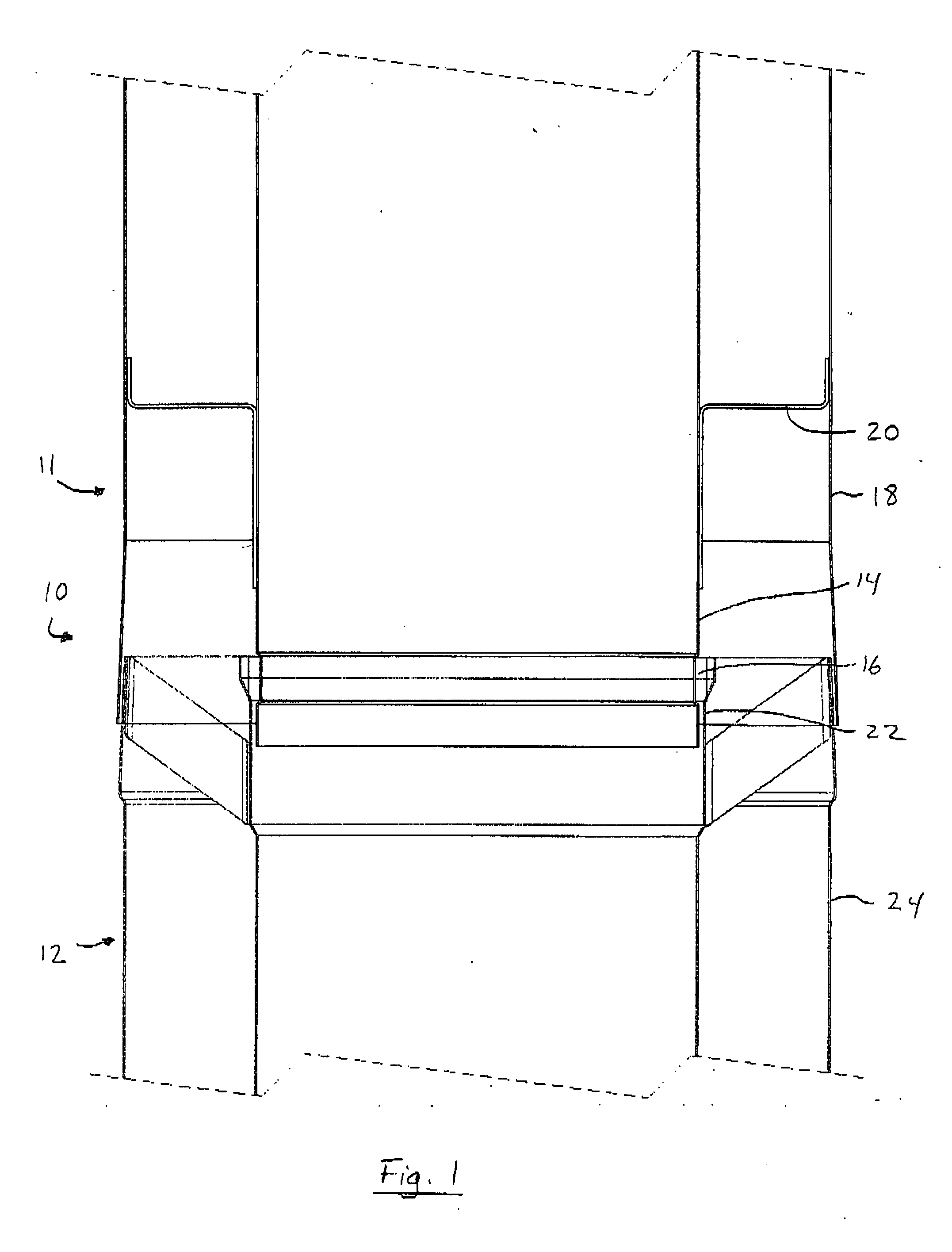
[0103] In accordance with the present invention and as illustrated in FIG. 1, there is provided a pipe coupling 10 for components of a venting system comprising a male pipe member 11 on an end of a first component and a female pipe member 12 on a corresponding end of a second component. The male pipe member 10 comprises an inner flue pipe 14 having a compressible gasket 16 surrounding the inner flue pipe 14 proximate an external end of the inner flue pipe 14, an external venting pipe 18 surrounding the inner flue pipe 14 and brackets 20 linking the inner flue pipe 14 to the external venting pipe 18. The female pipe member 12 receives the male pipe member 11 and comprises an inner flue sleeve 22 being sized larger than the outer diameter of the inner flue pipe at an outer end of the sleeve 22 and a second external venting pipe 24 surrounding the inner flue sleeve 22. The inner flue sleeve 22 remains in circumferential contact with the compressible gasket 16, and the first 18 and seco...


PUM


Abstract

A pipe coupling for components of a venting system comprising a male pipe member on an end of a first component and a female pipe member on a corresponding end of a second component. The male pipe member comprises an inner flue pipe having a compressible gasket surrounding the inner flue pipe proximate an external end of the inner flue pipe, an external venting pipe surrounding the inner flue pipe and brackets linking the inner flue pipe to the external venting pipe. The female pipe member receives the male pipe member and comprises an inner flue sleeve being sized larger than the outer diameter of the flue pipe at an outer end of the sleeve. The inner flue sleeve remains in circumferential contact with the compressible gasket when the male pipe member is inserted into the female pipe member.

Description

FIELD OF THE INVENTION [0001] The present invention is directed to a venting system. More particularly, the present invention is directed to a coupling for a direct venting system for fireplaces and stoves. The present patent application claims priority of U.S. 60 / 780,062 filed Mar. 8, 2006, the contents of which are incorporated herein by reference. BACKGROUND OF THE INVENTION [0002] Direct-vent gas fireplaces or stoves solve many of the problems associated with wood-burning forebears. Unlike traditional masonry fireplaces with foundations and chimneys, direct-vent units take advantage of technologies that allow small clearances. These systems are typically prefabricated from metal and designed to be installed in wood-frame constructions without a foundation or a chimney. As the direct-vent systems burn efficiently, combustion gases can be vented directly out a wall. These systems are much easier and less expensive to install than masonry units and allow much greater flexibility in...

Claims


Application Information

Patent Timeline
27 Sep 2007
Publication
US20070221195A1
IPC
F24C1/14
CPC
F23J13/04; F24C15/20; F23J2213/202; F23J2211/10
Inventors
BIBAUD, ANDRE; GILBERT, LUC