
Method and Apparatus for Reducing the Amount of Sludge Produced in a Pulp and/or Paper Mill

a technology of pulp and paper mills and sludge, which is applied in the direction of lighting and heating equipment, sludge treatment by oxidation, and separation processes, etc. it can solve the problems of smelting explosion hazards, affecting the efficiency of boilers, and requiring a great deal of accuracy in burning sludge in recovery boilers, so as to reduce the amount of sludge and reduce the processing load of waste water plants of the aforementioned mills.

Inactive Publication Date: 2007-09-27
VALMET TECH INC
View PDF7 Cites 5 Cited by
  • Summary
  • Abstract
  • Description
  • Claims
  • Application Information

AI Technical Summary

Benefits of technology

[0010] Thus, the purpose of the present invention is to produce a method for reducing the amount of sludges produced in a pulp and / or paper mill, said method avoiding said problems and enabling the disposal of sludges produced in the pulp and paper mill as a result of treating waste waters in such a manner that a larger amount of sludge than before can be disposed of by means of burning. Furthermore, the processing load of the waste water plants of the aforementioned mills can be reduced at the same time. Furthermore, it is an aim of the invention to provide an apparatus implementing the aforementioned method.
[0015] The fuel is heated by means of primary or secondary heating media available in a pulp and / or paper mill into a temperature of over 100° C., whereafter the sludge, whose dry matter content is 20 to 25%, is mixed therein. The sludge, having a lower temperature cools down the hot fuel, which, while cooling down, absorbs sludge and the particles contained therein within itself. In the process of heating the fuel, primary heating media are mainly used, said media being obtained from the mill. These include hot gases obtained directly from the different steam lines or the turbine of the mill, which gases can be hot air, hot steam, such as counterpressure steam of the turbine, steams from the power boiler or recovery boiler, or flue gases from the power boiler or recovery boiler of the mill. It is also possible to utilize secondary heating media in the heating, such as hot gases produced by means of a heat exchanger from the condensates and gases obtained from different process stages. The heating of the fuel not only results in that the fuel dries, but also in that the water inside the pieces of wood chips and bark becomes vaporized. The hot steam inside the fuel particles improves their capability to absorb sludge within themselves. Thereafter, the fuel-sludge mixture is conveyed to be burned in the power boiler. The solid fuel supplied to the power boiler by means of the invention is capable of retaining more sludge than solutions of prior art. Thus, it is possible to dispose of a larger amount of sludge by burning and the amount of sludge to be disposed of by taking it to a waste disposal site or in other ways is reduced. Furthermore, the processing load of the waste water plant of the mill is reduced. Furthermore, it brings about positive economical effects by reducing the operating costs of the mill through reduced waste water costs. By means of the method according to the invention it is also possible to improve the heat economy of paper mills by using the different hot secondary heating media produced in different unit processes to heat and dry the fuels.

Problems solved by technology

In these waste disposal methods problems are still caused by the high moisture content of the sludge that impairs the efficiency of the boiler.
The burning of sludge in the recovery boiler also requires great deal of accuracy, because the large variations in the dry matter content of the sludge may cause a smelt explosion hazard.
As was mentioned above, problems are caused by the water contained in the sludge, which impairs the efficiency of the power boiler burning the sludge.
Tightening environmental requirements that pose restrictions for the amount of sludge to be placed in the waste disposal site result in that it is necessary to dispose of a larger amount of waste by means of other methods.

Method used


Image

  • Method and Apparatus for Reducing the Amount of Sludge Produced in a Pulp and/or Paper Mill
  • Method and Apparatus for Reducing the Amount of Sludge Produced in a Pulp and/or Paper Mill
  • Method and Apparatus for Reducing the Amount of Sludge Produced in a Pulp and/or Paper Mill

Examples


Embodiment Construction

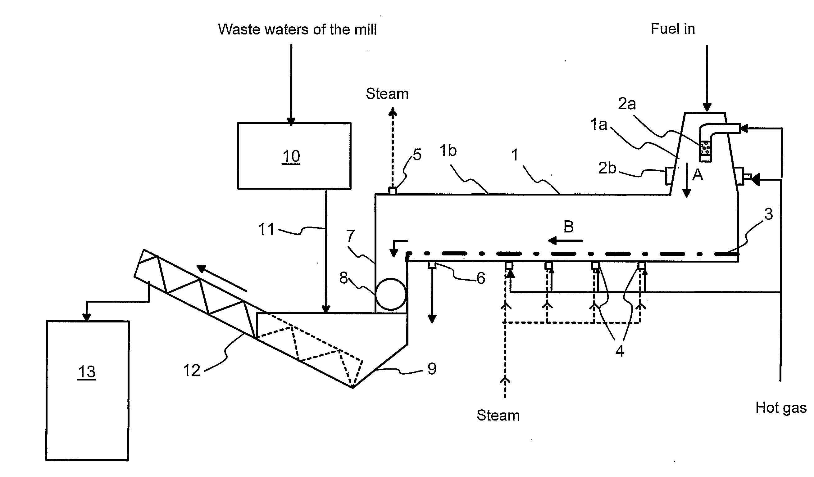
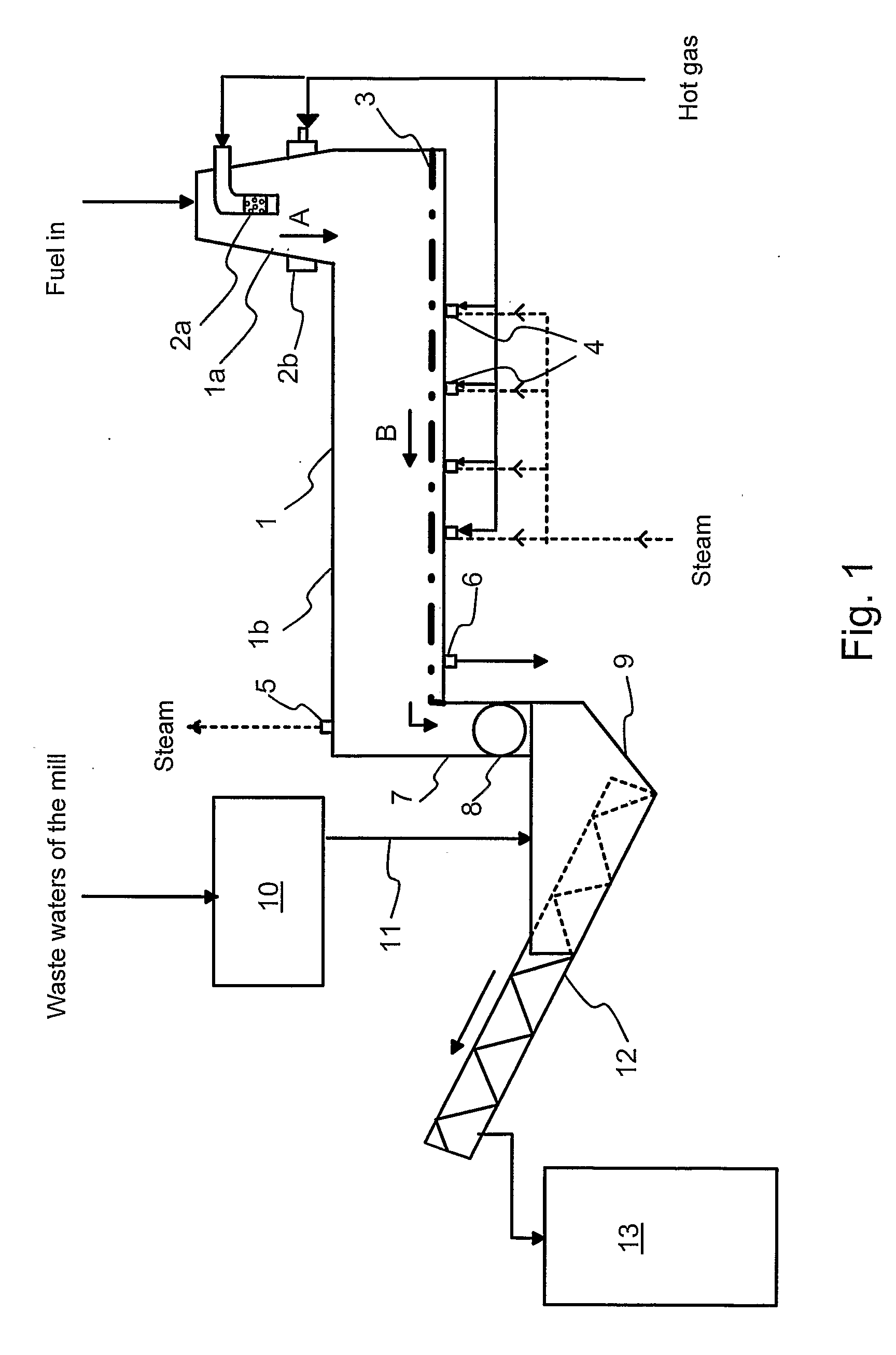
[0020]FIG. 1 shows schematically an apparatus according to the invention for reducing the amount of sludges in a pulp or paper mill. The apparatus comprises heating means 1 for solid fuel, i.e. a steaming apparatus in which the fuel is heated and moisture is removed therefrom by means of hot gas obtained from the pulp or paper mill.

[0021] The fuel is supplied to the steaming apparatus 1 from the fuel storage bin, or if the fuel consists of wood chips, directly from chipping (not shown in the drawing). In the embodiment shown in FIG. 1, the heating of the fuel takes place in two stages. In the first fuel heating phase the wood chips are conveyed to a vertical first heating part 1a of the steaming apparatus 1 from its upper end. The fuel moves in the first heating part by means of gravity vertically downward according to the arrow A. Hot gas is conveyed to the first heating part 1a crosswisely with respect to the fuel flow from gas feeding pipes 2a and 2b. The feeding pipes are equip...


PUM

PropertyMeasurementUnit
Temperatureaaaaaaaaaa
Fractionaaaaaaaaaa

Abstract

The amount of sludges produced in a pulp and / or paper mill is reduced. The sludge produced in a pulp and / or paper mill as a result of waste water treatment is conveyed to solid fuel and the produced fuel-sludge mixture is burned in a power boiler. The solid fuel is heated before sludge is mixed therein.

Description

FIELD OF THE INVENTION [0001] The invention relates to a method according to the preamble of the appended claim 1 for reducing the amount of sludges produced in a pulp and / or paper mill. The invention also relates to an apparatus for implementing the aforementioned method in accordance with the preamble of the appended claim 9. BACKGROUND OF THE INVENTION [0002] In pulp and paper mills different kinds of sludges and waste waters are produced in various process stages in connection with the manufacture of the end product. These include for example waste waters produced in the wood room and in chipping, waste waters produced in pulping, in cleaning processes of the produced pulp and in other treatments, as well as sludges and waste waters produced in connection with paper-making. At present, the aim is to recover as large an amount as possible of the fibers that have ended up in these sludges and waste waters and to recycle the fibers back to the process, such as paper-making. The rem...

Claims


Application Information

Patent Timeline
IPC IPC(8): D21C11/12D21F5/18C02F11/06C02F11/14
CPCC02F11/06C02F2103/28C02F11/14C02F11/147Y02W10/40
Inventor LAMPINEN, RAMI
Owner VALMET TECH INC
Learn More