Electromagnetic actuator for active vibration damping device

a technology of electromagnetic actuator and actuator, which is applied in the direction of shock absorbers, machine supports, jet propulsion mountings, etc., can solve the problems of excessive displacement of movable parts, undesirable noise or damage of actuators, and devices that cannot exhibit desired vibration damping, so as to reduce or avoid damage, improve operation stability and durability, and avoid an increase in the number of parts

Active Publication Date: 2007-09-27
SUMITOMO RIKO CO LTD
View PDF6 Cites 16 Cited by
  • Summary
  • Abstract
  • Description
  • Claims
  • Application Information

AI Technical Summary

Benefits of technology

[0010]It is therefore one object of this invention to provide an electromagnetic actuator for active vibration damping devices of a new constitution, that is able to realize both a stopper mechanism that is excellent for limiting displacement of an oscillation rod when there is excessive external input, and a sealing mechanism of the housing bottom wall part, with a small number of components and a simple constitution.
[0013]According to the electromagnetic actuator of above described construction for active vibration damping devices, the first stopper unit and the second stopper units of the integrally molded stopper are arranged beneath the coupling rod and the movable member, the displacement in the axial direction of the coupling rod and the movable member are limited by contact with the first stopper unit and the second stopper unit. This arrangement makes it possible, during operation of shock force and the like, to effectively reduce or avoid the occurrence of damage, abnormal sound or the like due to excessive displacement of the coupling rod or the movable member. In addition, since the second separation distance between the facing surfaces of the second stopper units and the movable member is greater than the first separation distance between the facing surfaces of the first stopper unit and the coupling rod, the stopper effect by the contact of the first stopper unit and the coupling rod and the stopper effect by the contact of the second stopper units and the movable member are provided in a stepwise fashion. Thus, it is possible to more advantageously obtain a displacement limiting effect with the compound stopper effect of the stopper units.
[0014]Further, at the outer periphery part of the integrally molded stopper, the ring shaped sealing unit is formed, and by having grip pressure of the ring shaped sealing unit between the housing bottom wall part and the lid member, the opening of the adjustment hole formed on the bottom wall part of the housing is fluid-tightly closed. With this arrangement, penetration of dust, water or the like from the outside through the adjustment hole is prevented, and it is possible to advantageously improve the operation stability and durability. In particular, by using a integrally molded stopper by integrally molding of the ring shaped sealing unit and the first and second stopper units using a rubber elastic body, it is possible to realize with a single part the sealing function and the stopper function, and while avoiding an increase in the number of parts. This makes it possible to obtain both an effective seal and stopper effect.
[0015]In one preferred form of the first aspect of the invention, the ring shaped sealing unit, the coupling unit, and the second stopper unit formed aligning on a plane spreading radially outwardly from a center in a thickness direction of an outer circumferential surface of the first stopper, and the integrally molded stopper is mounted in a state with the ring shaped sealing unit displaced to one side in the thickness direction of the first stopper unit. According to this arrangement, the ring shaped sealing unit is in the state displaced to one side in the thickness direction of the first stopper unit when the integrally molded stopper is mounted between the housing and the lid member, so that the coupling unit that couples the ring shaped sealing unit and the first stopper unit is elastically deformed. Based on this elastic deformation, there is an elastic force effect downward in the axial direction on the first stopper unit which is the center part of the integrally molded stopper. Therefore, the first stopper unit is pressed against the lid member, thereby being stably supported by the lid member fixed to the housing. This makes it possible to obtain a stable desired elastic stopper effect during contact of the coupling rod. Preferably, the thickness dimension of the first stopper unit is greater than the thickness dimension of any of the ring shaped sealing unit, the coupling unit, and the second stopper units.
[0016]In another preferred form of the first aspect of the invention, the second stopper unit comprises an elastic abutting unit disposed axially beneath the movable member, and an elastic support unit extending diametrically inwardly from the ring shaped sealing unit for elastically connecting the elastic abutting unit with respect to the ring shaped sealing unit. This arrangement allows the second stopper unit to be less likely to be influenced by the elastic deformation of the first stopper unit, such as floating up, making it possible to have the movable member come into contact against the second stopper at a predetermined position with stability, thereby exhibiting desired shock absorbing effect. Also, when the ring shaped sealing unit is mounted in a state displaced to one side of the thickness direction of the first stopper unit, it is possible to prevent arrangement of the second stopper unit in a state separated from the lid member by forming the second stopper unit so as to be extended out from the ring shaped seal unit side. This makes it possible to advantageously exhibit a stable stopper effect using the second stopper unit. Preferably, the elastic abutting unit has a wall thickness greater than that of the elastic support unit, and is supported in a cantilevered state by the ring shaped sealing unit via the elastic support unit.
[0017]In yet another preferred form of the first aspect of the invention, the coupling unit comprises spoke units radially extending at a plurality of circumferential locations to have the first stopper unit and the ring shaped sealing unit coupled integrally by the spoke units, and wherein adjacent ones of the spoke units are circumferentially spaced from one another via hollow parts formed therebetween, and wherein the second stopper units are positioned at centers in the circumferential direction of the hollow parts, respectively. According this preferred form, the second stopper units are positioned at the center between the circumferential direction of the spoke units, making it possible to advantageously avoid inhibition of the elastic deformation of the second stopper unit due to contact with the spoke units, and making it possible to effectively obtain the stopper effect using the second stopper unit.

Problems solved by technology

These known vibration damping devices exhibit passive vibration damping effects, so that these known devices are not able to exhibit desired vibration damping effect when frequency characteristics of vibration to be damped varies, or when a higher level of vibration damping effect is required.
When a large impact or the like acts as the external force on the active vibration damping device equipped with this kind of electromagnetic actuator, the movable member may displace excessively, possibly striking against the housing or the like.
This striking of the movable member may possibly cause undesirable noise or impacts, leading to undesirable noise or damage of actuator itself.
However, this kind of simple rubber sheet may not realize sufficient shock absorption, when a large shock load is applied on the active vibration damping device.
Further, the repeated striking of the movable member against the housing may deteriorate the durability of the rubber sheet, leading to damage of rubber sheet it self.
Through this adjustment hole, if foreign matter such as dust or water or the like penetrates from the outside, smooth excitation displacement of the movable member is deterrent, making it impossible to obtain the initially generated oscillation force, or leading to a deterioration of durability or the like due to erosion or the like.
However, this kind of sealing constitution needs a separate sealing rubber, thereby increasing the number of components, possibly leading to a problem of a reduction in productivity and the like.

Method used


Image

  • Electromagnetic actuator for active vibration damping device
  • Electromagnetic actuator for active vibration damping device
  • Electromagnetic actuator for active vibration damping device

Examples


Embodiment Construction

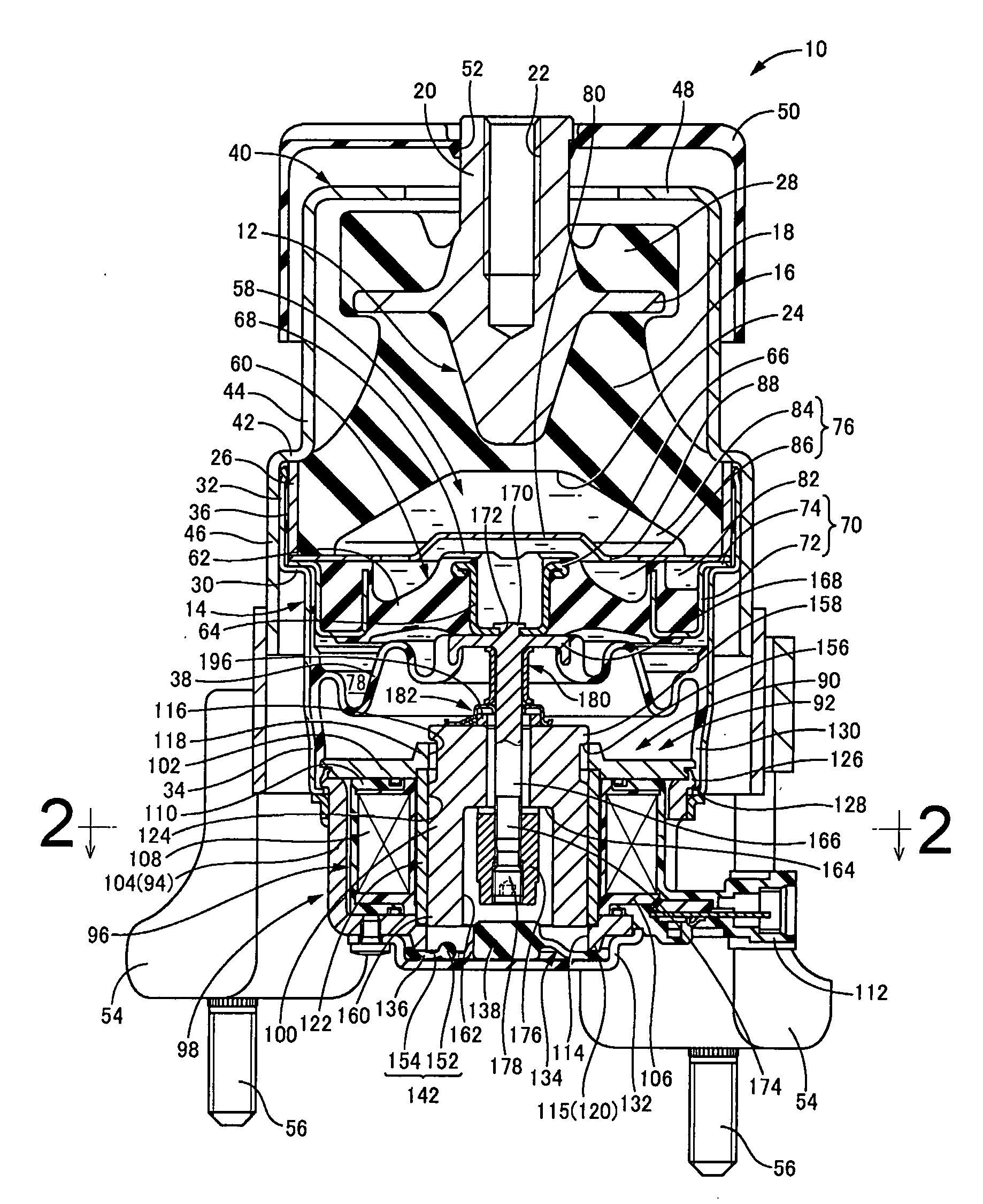
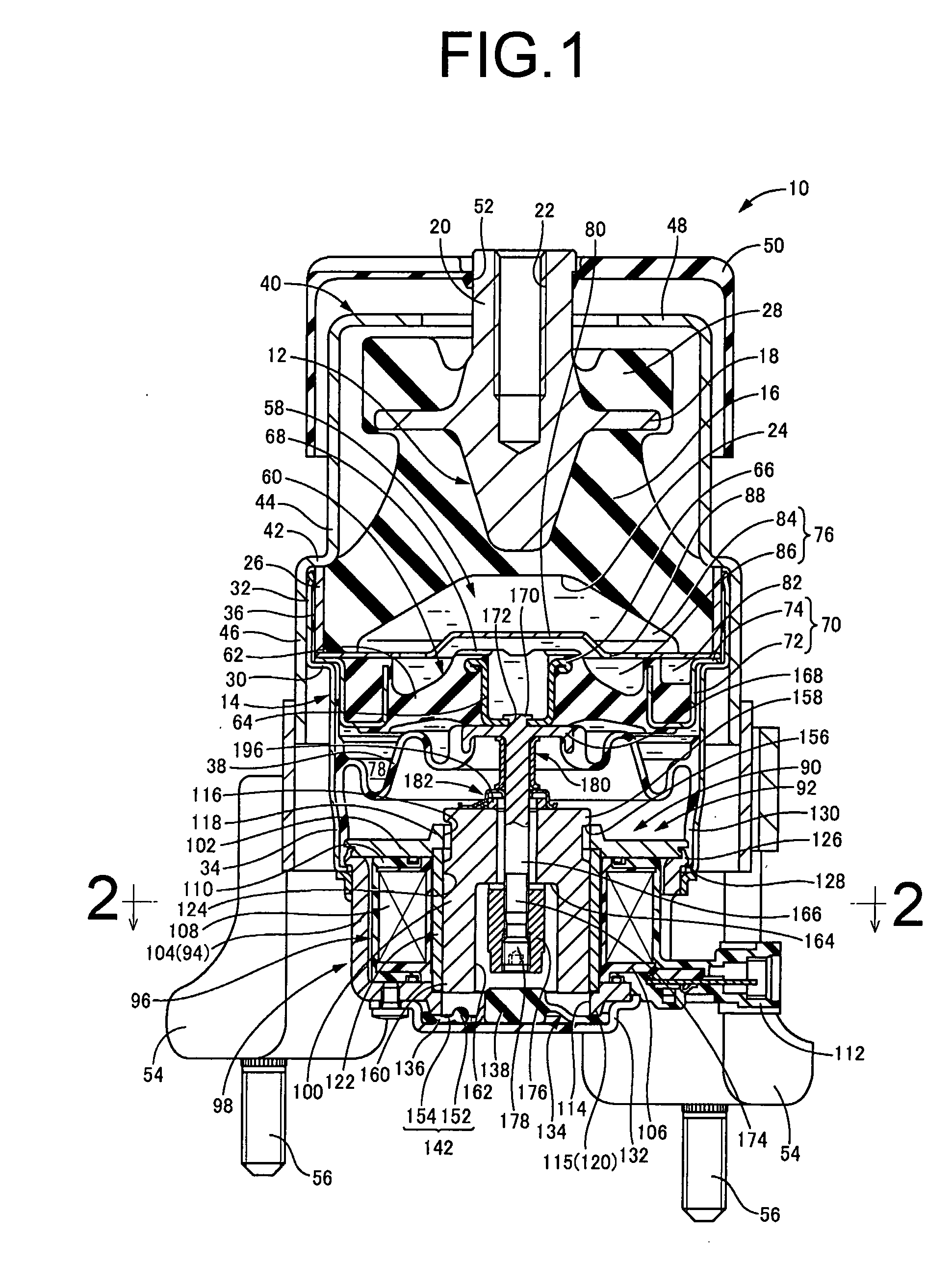
[0024]Referring first to FIG. 1, there is shown an automotive engine mount 10 equipped with an electromagnetic actuator 90 of construction according to a first embodiment of the present invention. The engine mount 10 includes a metallic first mounting member 12 and a metallic second mounting member 14, which are positioned in opposition and spaced apart from each other in the axial direction, and elastically connected by means of a main rubber elastic body 16 interposed between them. With the first mounting member 12 attached to a power unit (not shown) and the second mounting member 14 attached to an automobile body (not shown), the power unit is supported on the body in a vibration-damped manner via the engine mount 10. In this installed state, the distributed load of the power unit is exerted on the engine mount 10, across the first mounting member 12 and the second mounting member 14 in the mounting center axis direction, which is the vertical direction in FIG. 1, whereby the ma...


PUM


Abstract

An electromagnetic actuator having: a stator and a movable member disposed in a central hole of a coil member of the stator movable in an axial direction; a coupling rod fixed to the movable member; and an elastic stopper having a ring shaped sealing unit at its outer periphery part, a first stopper unit at its center part, a coupling unit that mutually couples the sealing unit and the first stopper unit, and second stopper units located radially between the sealing unit and the first stopper unit at respective circumferential positions. The sealing unit is compressed between the bottom wall of a housing and a lid member to form a sealing mechanism that fluid-tightly close an opening of an adjustment hole. The first stopper unit axially faces the coupling rod bottom with a first separation distance, and the second stopper units axially face the movable member bottom with a second separation distance greater than the first.

Description

INCORPORATED BY REFERENCE[0001]The disclosure of Japanese Patent Application No. 2006-063127 filed on Mar. 8, 2006 including the specification, drawings and abstract is incorporated herein by reference in its entirety.BACKGROUND OF THE INVENTION[0002]1. Field of the Invention[0003]The present invention relates to an electromagnetic actuator that can be suitably used for active vibration damping devices such as a vibration damping mount, damper or the like that exhibits an active damping effect.[0004]2. Description of the Related Art[0005]In order to reduce vibration in members subject to vibration damping such as an automobile body or the like for which vibration reduction is viewed as important, there are typically employed vibration damping devices such as vibration damping means utilizing attenuation effect of a shock absorber, a rubber elastic body or the like, and vibration insulation means utilizing spring effect of a coil spring, a rubber elastic body or the like. These known...

Claims


Application Information

Patent Timeline
Patent Type & Authority Applications(United States)
IPC IPC(8): F16F15/00
CPCF16F13/26F16F13/106B60K5/1208B60K5/1283F16F13/16F16F13/264
Inventor ICHIKAWA, HIROYUKIWATANABE, YOSHINORIYASUDA, TAKAYOSHISAKURAI, MOTOSHI
Owner SUMITOMO RIKO CO LTD
Why Eureka
Try Eureka