
Optical pickup and optical disc drive

a pickup and optical disc technology, applied in the field of optical pickup and optical disc drives, can solve the problems of deteriorating information signal quality, affecting the quality of information signal, so as to achieve satisfactory signal quality

Inactive Publication Date: 2007-09-27
HITACHI MEDIA ELECTORONICS CO LTD
View PDF5 Cites 25 Cited by
  • Summary
  • Abstract
  • Description
  • Claims
  • Application Information

AI Technical Summary

Benefits of technology

[0007]The present invention has been made in view of the foregoing problems and it is therefore an object of the present invention to provide an optical pickup for writing information to and / or for reading information from an optical disc having at least two recording layers provided with first and second recording layers, capable of preventing a reflected light beam reflected from the second layer from affecting a reproduced signal or a servo signal while information is being read from the first layer, of preventing the reduction of the intensity of a reflected light beam reflected from the first recording layer and of insuring a satisfactory signal quality. Another object of the present invention is to provide an optical disc drive provided with the optical pickup according to the present invention.
[0012]The present invention provides the reliable optical pickup for writing information to and / or for reading information from an optical disc having at least two recording layers, capable of insuring a satisfactory signal quality, and the optical disc drive provided with this optical pickup.

Problems solved by technology

Therefore, the intensity of the main beam reflected from the second recording layer is unignorably high to the sub beam and hence the main beam reflected from the second layer can be a significant disturbance to the sub beam reflected from the first layer during a writing information to or reading information from first recording layer operation.
However, since the reflected light beam from the first recording layer and the light beam from the second recording layer travel along one and the same optical axis, part of the reflected light beam from the first recording layer which is not desired to be diffracted is also diffracted when the reflected light from the second recording layer is diffracted and, consequently, the intensity of the light beam to be detected drops.
When the intensity of the light beam to be detected drops, the quality of an information signal deteriorates.

Method used


Image

  • Optical pickup and optical disc drive
  • Optical pickup and optical disc drive
  • Optical pickup and optical disc drive

Examples


first embodiment

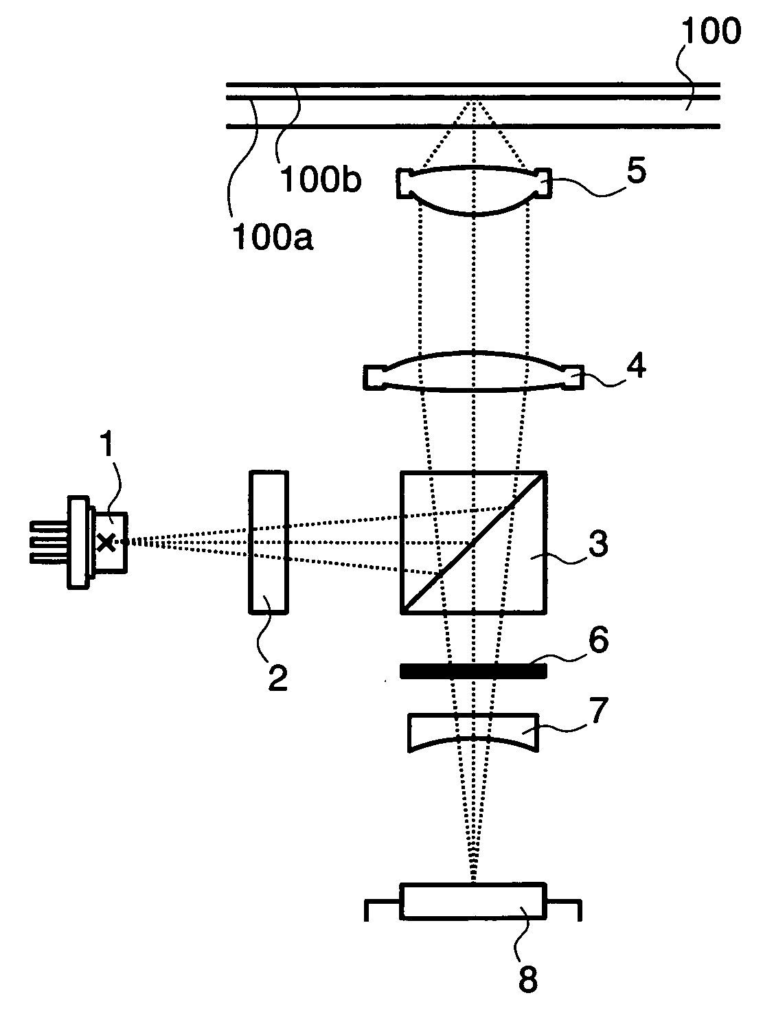
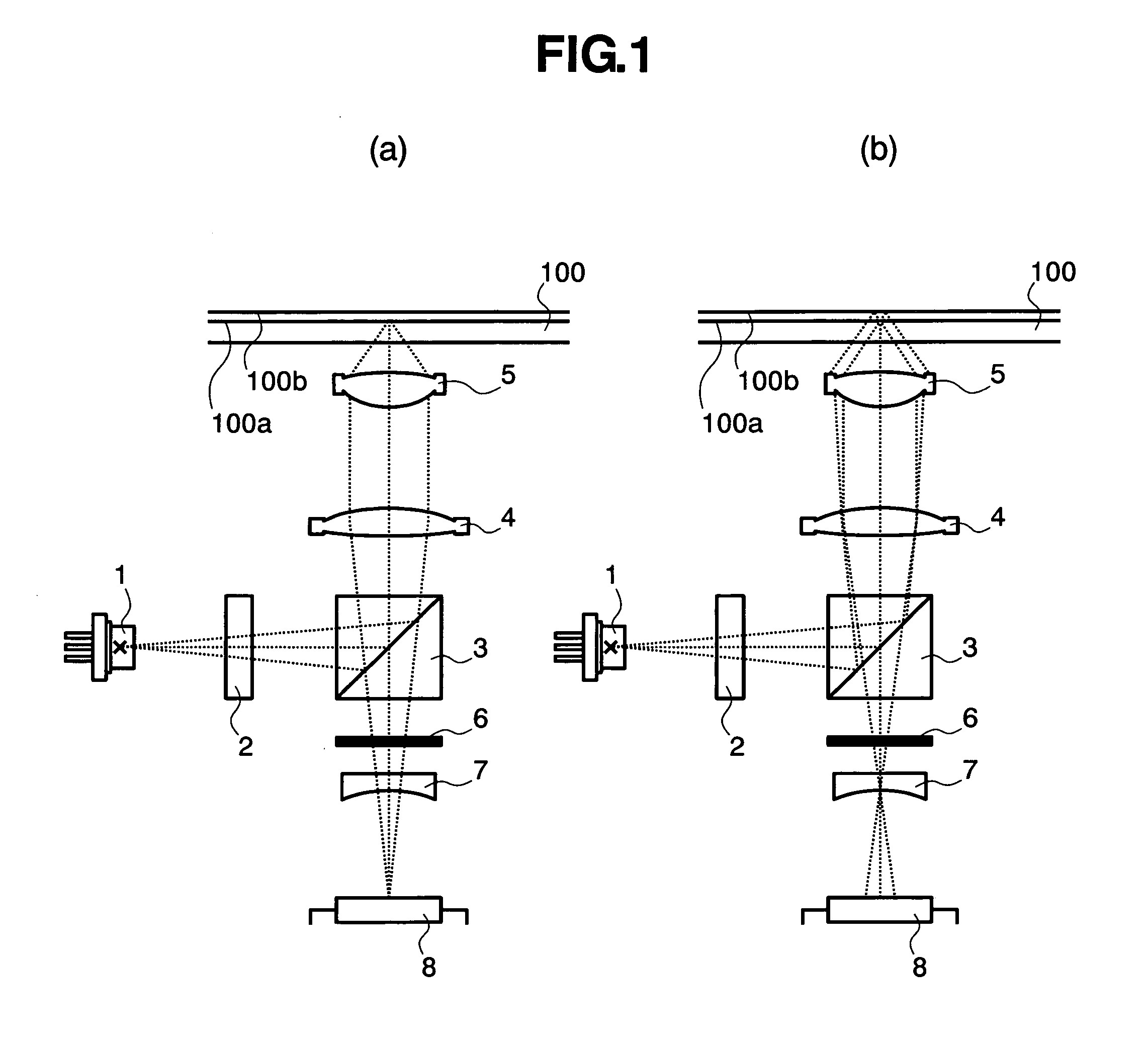
[0026]FIG. 1 shows an optical pickup adopting a servo signal detection system in a first embodiment according to the present invention using three beams in a preferred embodiment according to the present invention. Referring to FIG. 1(a), the optical pickup includes, as principal components, a laser diode 1 that emits a light beam of a wavelength λ, an objective lens 5 for focusing the light beam on an optical disc 100, a polarization switch 6 for changing the polarization direction of part or all of the light beam, and a detector 8 for detecting the light beam reflected from the optical disc 100.

[0027]A diffraction grating 2 diffracts the light beam of the wavelength λ emitted by the laser diode 1 to provide at least three light beams. A beam splitter 3 reflects the three light beams. The light beams reflected by the beam splitter 3 are collimated in substantially parallel light beams by a collimating lens 4. The objective lens 5 focuses the collimated light beams on the optical di...

third embodiment

[0045]The wave plate pattern in the third embodiment is not limited to a rectangle and may be a rhombus, a parallelogram or a polygon.

[0046]An optical pickup in a fourth embodiment according to the present invention will be described. The optical pickup in the fourth embodiment has a striped wave plate pattern as shown in FIG. 8.

fourth embodiment

[0047]FIG. 9(a) illustrates a distribution pattern of polarization when the light beam for reproduced signal detection or servo signal detection is focused on the light-receiving surfaces. FIG. 9(b) illustrates a distribution pattern of polarization of the light beam acting as a disturbance. The direction of polarization of the light beam irradiating light regions shown in FIGS. 9(a) and 9(b) and that of the light beam irradiating dark regions shown in FIGS. 9(a) and 9(b) are perpendicular to each other. Therefore, although the polarization switch 6 employed in the fourth embodiment forms a region in which the respective directions of polarization of the light beams for reproduced signal detection or servo signal detection and the beam acting as a disturbance are perpendicular to each other in a small area, the polarization switch 6 has a low sensitivity to the performance-deteriorating effect of its horizontal dislocation as viewed in FIG. 8.

[0048]The stripes do not need to be arra...


PUM


Abstract

An optical pickup for writing information to and / or for reading information from an optical disc having at least two recording layers (dual layer) provided with first and second recording layers can prevent layer crosstalk resulting from disturbing a signal reproduced from the first recording layer by a reflected light beam reflected from the second recording layer during a writing operation for writing information to the first recording layer or a reading operation for reading information from the fist recording layer. An orthogonal polarization region forming component forms an orthogonal polarization region, in which respective directions of polarization of a first light beam focused on and reflected by a first recording layer of an optical disc and a second light beam reflected by a second recording layer of the optical disc are perpendicular to each other, in a region, in which the first and the second light beam overlap each other, on a light-receiving surface of a detector. The orthogonal polarization region forming component is a polarization switch for changing the directions of polarization of part or all of the first and the second light beam.

Description

BACKGROUND OF THE INVENTION[0001]The present invention relates to an optical pickup for reading information from an optical disc having at least two recording layers, and an optical disc drive provided with this optical pickup.DESCRIPTION OF THE RELATED ART[0002]An optical pickup for writing information to and / or for reading information from an optical disc having a plurality of recording layers (at least two recording layers) on one side thereof is disclosed in, for example, Patent document 1 (p. 10). This known optical pickup is provided with an optical component capable of suppressing the detection of light from the adjacent recording layer by a detector and this optical pickup prevent fluctuation of output signal which is caused by light from the adjacent recording layer. The optical component is provided with a diffracting area for diffracting part of light reflected from the adjacent recording layer when the optical pickup is applied to writing and / or reading information to an...

Claims


Application Information

Patent Timeline
IPC IPC(8): G11B7/00
CPCG11B7/0903G11B2007/0013G11B2007/0006G11B7/1367
Inventor SHIMADA, KENICHIOHNISHI, KUNIKAZUKONUMA, NOBUHIRO
Owner HITACHI MEDIA ELECTORONICS CO LTD
Features
  • Generate Ideas
  • Intellectual Property
  • Life Sciences
  • Materials
  • Tech Scout
  • Unparalleled Data Quality
  • Higher Quality Content
  • 60% Fewer Hallucinations
Learn More