
Non-aqueous electrolyte battery

a technology of electrolyte battery and non-aqueous electrolyte, which is applied in the direction of non-aqueous electrolyte cells, wound/folded electrode electrodes, sustainable manufacturing/processing, etc., can solve the problems of large amount of heat generated, large short-circuit current, and short-circuiting, so as to prevent heat generation

Inactive Publication Date: 2007-09-27
HITACHT MAXELL LTD
View PDF6 Cites 20 Cited by
  • Summary
  • Abstract
  • Description
  • Claims
  • Application Information

AI Technical Summary

Benefits of technology

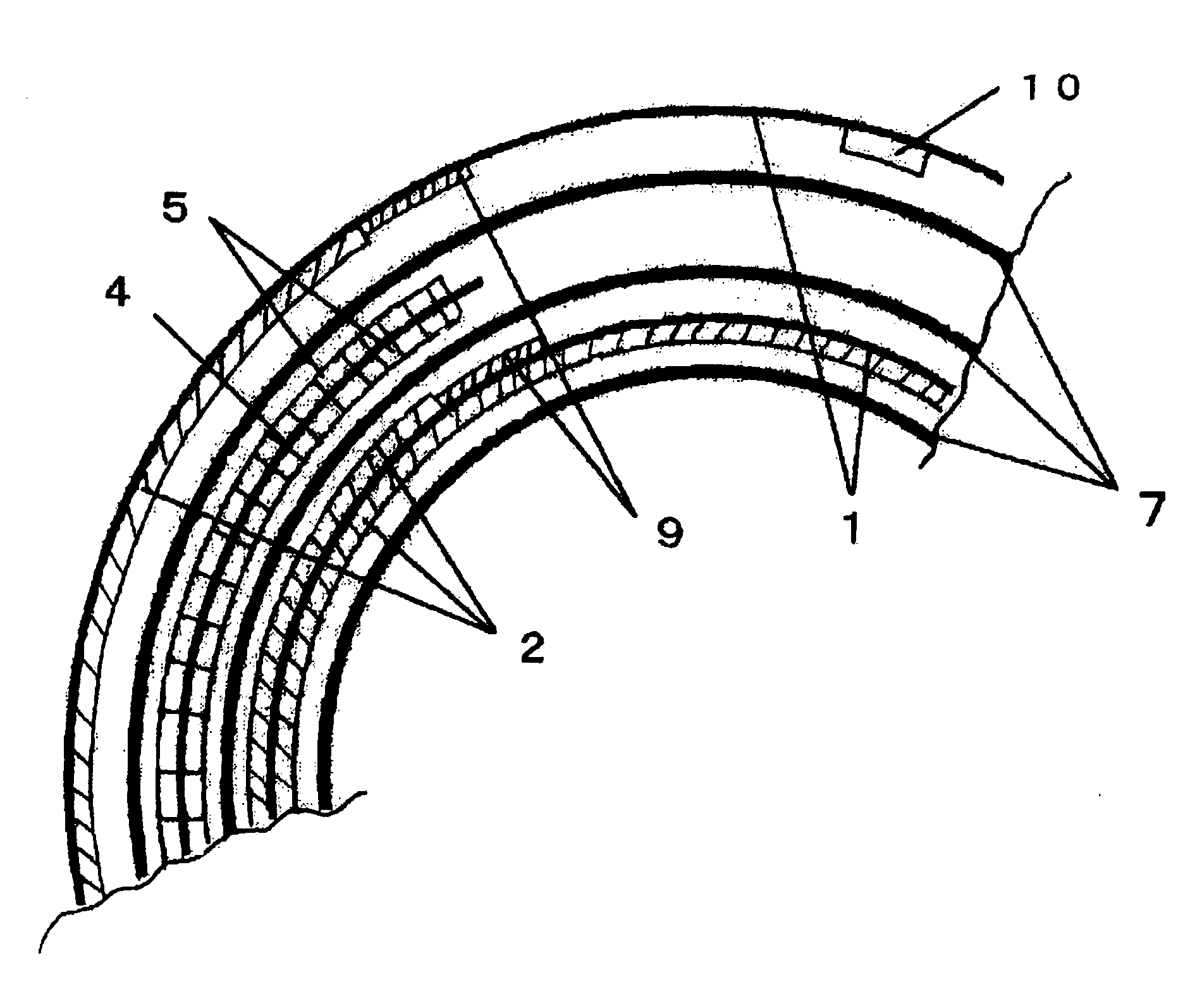
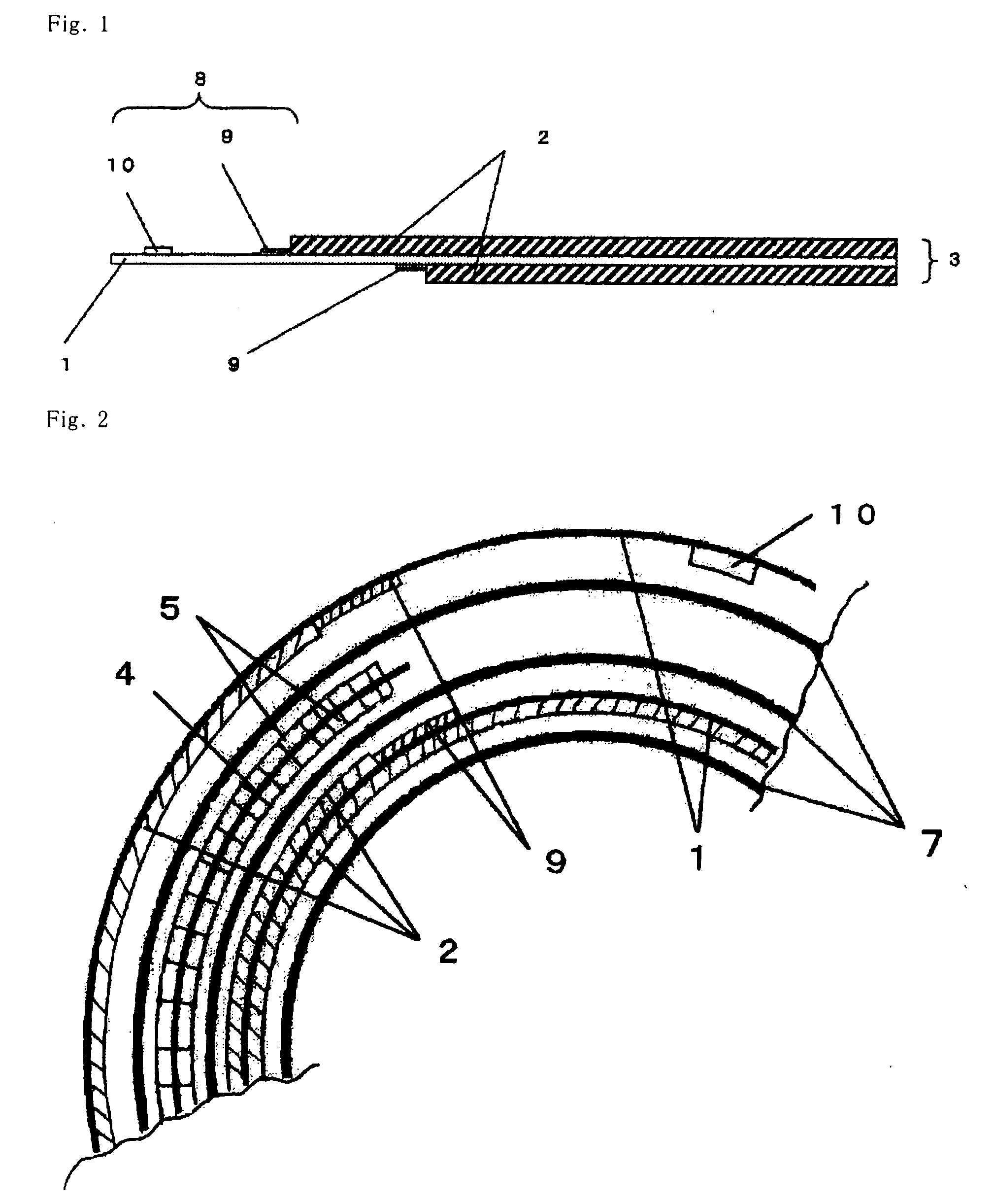
[0010] One object of the present invention is to provide a non-aqueous electrolyte battery which does not have any unnecessary exposed portion of a current collector of a positive electrode, and has a robust insulating layer which is formed at a part where the exposed portion of the current collector of the positive electrode faces a negative electrode through a separator, whereby an accident caused by heat generation is prevented even when short circuiting occurs.

Problems solved by technology

If the separator is damaged or it is moved from the right position when the battery is shocked, the positive and negative electrodes may be brought into contact with each other to cause short circuiting.
However, when the negative electrode and the exposed portion of the current collector of the positive electrode are brought into contact each other, the amount of heat generated is large since the electric resistance of the current collector is small and thus the short-circuit current is large.
In particular, the contact between the exposed portion of the current collector of the negative electrode and that of the current collector of the positive electrode is dangerous since it is the contact of metal parts so that the short-circuit current becomes very large.
If they are short circuited, the amount of heat generated is large so that the potential of a risk such as ignition and explosion increases.
Therefore, the thickness of the insulating tape increases the total thickness of the battery, and may have any adverse influence on the designing of a battery having a smaller thickness.
However, when the insulating layer is made of a single resin having a high crystallinity such as PVdF, the resin molecules shrink during the evaporation of the solvent and thus the film of PVdF shrinks.
When the hard powder particles having a melting point of 500° C. or higher is used, the shrinkage of the coated film may be prevented to some extent, but the resin film becomes brittle.
Such a problem remarkably arises at the edge of the current collector foil, and the desired insulating effect is not attained.

Method used


Image

  • Non-aqueous electrolyte battery
  • Non-aqueous electrolyte battery
  • Non-aqueous electrolyte battery

Examples


example 1

[0040] Production of Positive Electrode

[0041] Eighty-five (85) parts by weight of LiCoO2 as a positive electrode active material, 10 parts by weight of acetylene black as a conductive assistant, and 5 parts by weight of PVdF as a binder were uniformly mixed with N-methyl-2-pyrrolidone (NMP) as a solvent to prepare a paste containing a positive electrode mixture. This paste was applied on both surfaces of a 15 μm thick aluminum foil as a current collector, so that the length of the active material applied onto the front surface was 280 mm and the length of the active material applied onto the back surface was 210 mm, and then dried to form positive electrode mixture layers on the current collector.

[0042] Then, the positive electrode mixture layers were calendered to adjust the total thickness of the current collector and the positive electrode mixture layers to 150 μm, and the current collector having the positive electrode mixture layers formed thereon was cut to form a positive e...

example 2

[0051] A non-aqueous secondary battery was produced in the same manner as in Example 1 except that the polyethylene powder was replaced with a polyethylene powder having an average particle size of 3 μm (FLO-BEADS LE1080 (trade name) manufactured by SUMITOMO SEIKA CHEMICALS Co., Ltd.) and that the thickness of the insulating resin layer was changed to 6 μm.

example 3

[0052] A non-aqueous secondary battery was produced in the same manner as in Example 1 except that the polyethylene powder was replaced with a polypropylene powder (PPW-5 (trade name) manufactured by SEISHIN ENTERPRISE Co., Ltd.; average particle size: 6 μm).


PUM

PropertyMeasurementUnit
thicknessaaaaaaaaaa
particle sizeaaaaaaaaaa
thicknessaaaaaaaaaa

Abstract

A non-aqueous electrolyte battery having an wound electrode body including a positive electrode having a layer of a positive electrode active material formed on a current collector, a negative electrode having a layer of a negative electrode active material formed on a current collector and a separator interposed between the positive electrode and the negative electrode, and a non-aqueous electrolyte, where the positive electrode has an exposed portion having no layer of the positive electrode active material at least at one of a winding-start edge and a winding-finish edge of the positive electrode so as to provide a lead member connected to an external terminal, an insulating layer of plural resins is formed on the exposed portion of the current collector of the positive electrode in a part in which the exposed portion of the current collector of the positive electrode faces that of the negative electrode via the separator, and the winding-start edge or the winding-finish edge of the positive electrode having no lead member has no exposed portion of the current collector.

Description

FIELD OF THE INVENTION [0001] The present invention relates a non-aqueous electrolyte battery. In particular, the present invention relates to a non-aqueous electrolyte battery which is suitably used as an electric source of a portable electronic device, a battery vehicle, a load leveling system, etc. BACKGROUND ART [0002] Lithium ion batteries, one example of non-aqueous electrolyte batteries, are widely used as the electric source of portable electric devices, for example, portable telephones, notebook-sized personal computers, etc., since they have a high energy density. Besides, the importance of secondary batteries which can be repeatedly charged has been increased out of consideration for environmental concerns. Thus, apart from the portable electric devices, the application of the lithium ion batteries to automobiles, electric wheeled chairs, domestic or commercial electricity storage systems, etc. is discussed. [0003] An existing lithium ion battery is produced by winding a ...

Claims


Application Information

Patent Timeline
Patent Type & Authority Applications(United States)
IPC IPC(8): H01M2/18H01M2/16H01M4/02H01M4/13H01M6/16H01M10/05H01M10/0587H01M50/531H01M50/586H01M50/595
CPCH01M2/26H01M2/34H01M2/347H01M4/131Y02E60/122H01M4/525H01M10/0587H01M2004/028H01M4/505Y02E60/10H01M50/579H01M50/531Y02P70/50H01M50/595H01M50/586H01M10/052H01M50/572H01M50/538H01M10/0431H01M4/13H01M2004/029
Inventor HIGUCHI, HAYATOABE, TOSHIHIRO
Owner HITACHT MAXELL LTD
Learn More