Protecting agent for image bearing member and production method therefor, protection layer forming apparatus, image forming method, image forming apparatus, and process cartridge

a protection agent and bearing member technology, applied in the field of protecting agents for image bearing members, can solve the problems of grainy images, occurrence of grainy images, abrasion of the image bearing member and scratches on its surface, etc., and achieve the effect of low effect on image quality and high quality

Active Publication Date: 2007-09-27
RICOH KK
View PDF8 Cites 45 Cited by
  • Summary
  • Abstract
  • Description
  • Claims
  • Application Information

AI Technical Summary

Benefits of technology

[0024]An object of the present invention is to provide an image bearing member protecting agent, which can protect an image bearing member from electrical stresses, generated from such as a charging step, and mechanical stresses, generated from such as the friction between the image bearing member and the cleaning blade, and wherein a deteriorated protecting agent, deterioration there

Problems solved by technology

Of those stresses, frictional stress generated at the cleaning process causes abrasion of the image bearing member and scratches on its surface.
The zinc oxidizes remaining at the surface have moisture-absorption characteristics and they absorb moisture existing in air with reducing resistance, so a static charge cannot be kept on the image bearing member under a high-humidity condition, and thus that may cause obscureness of a latent electric field image and an image failure, resulting in an occurrence of grainy images.
The products are then contained into a lubrication layer, reducing resistance under a high-humidity condition and may result in occurrences of grainy images.
As mentioned above, once low resistance substances are incorporated into the lubrication layer of the image bearing member, removing those substances requires removing the entire lubrication layer with, for example, a cleaning mechanism, and because of the slippery surface of the lubrication layer, removing requires great force and gives great amount of mechanical stress on the image bearing member itself.
However, a disadvantage of those toners is that a cleaning step, employing a cleaning blade such as a rubber cleaning blade, during which the surface o

Method used


Image

  • Protecting agent for image bearing member and production method therefor, protection layer forming apparatus, image forming method, image forming apparatus, and process cartridge
  • Protecting agent for image bearing member and production method therefor, protection layer forming apparatus, image forming method, image forming apparatus, and process cartridge
  • Protecting agent for image bearing member and production method therefor, protection layer forming apparatus, image forming method, image forming apparatus, and process cartridge

Examples


example 1

—Production of Image Bearing Member Protecting Agent 1—

[0325]The compositions of Protecting Agent No. 1 shown in Table 1 and Table 2 were contained in a glass container equipped with a lid and then molten using a temperature-controlled hot stirrer, holding its temperature at 120° C., while the compositions were agitated.

[0326]The molten compositions of Protecting Agent No. 1 were poured into a preheated aluminum mold at a temperature of 85° C. having internal dimension of 12 mm×8 mm×350 mm so that the mold was filled up with molten compositions, then allowed to stand to cool down to 50° C. under room temperature, re-heated in a constant-temperature bath, holding a constant temperature, to 60° C. and kept for 20 minutes at the temperature, and then stood to cool down to room temperature.

[0327]After cooling, solidified Protecting Agent No. 1 was detached from the mold, and shaped into a mass having its size of 7 mm×8 mm×310 mm in a cutting process, thus image bearing protecting agent ...

example 27

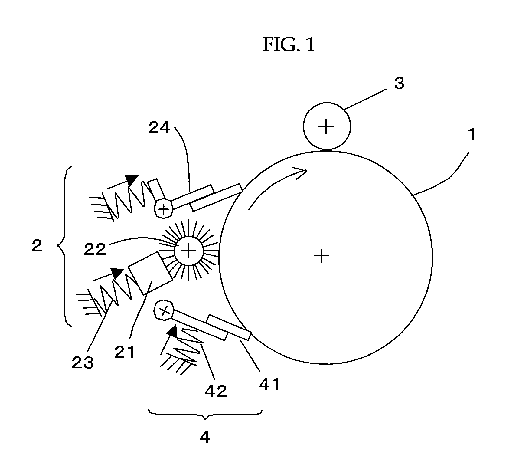
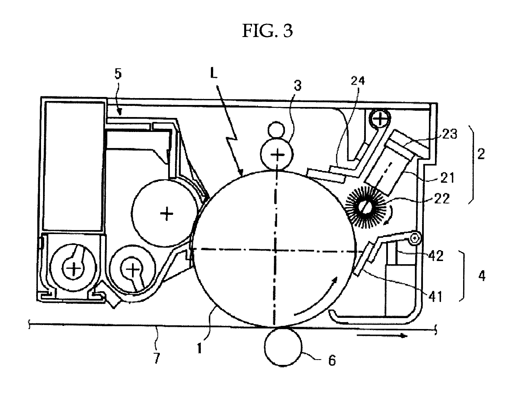
[0332]A process cartridge was composed of an image bearing member (or a photoconductor) having a surface layer thereon containing thermosetting resin (heat radical reactivity polyfunctional acrylic resin) and having thickness of 5 μm and a transferring unit, and the process cartridge further included a transfer unit, a counter type cleaning blade, a brush-shaped protecting agent supply member and a trailing-blade type protection layer forming member, which were arranged in an upstream order of the rotation direction of the image bearing member. The process cartridge also contained a protection layer forming apparatus that uses the image bearing member protecting agent 1 of Example 1.

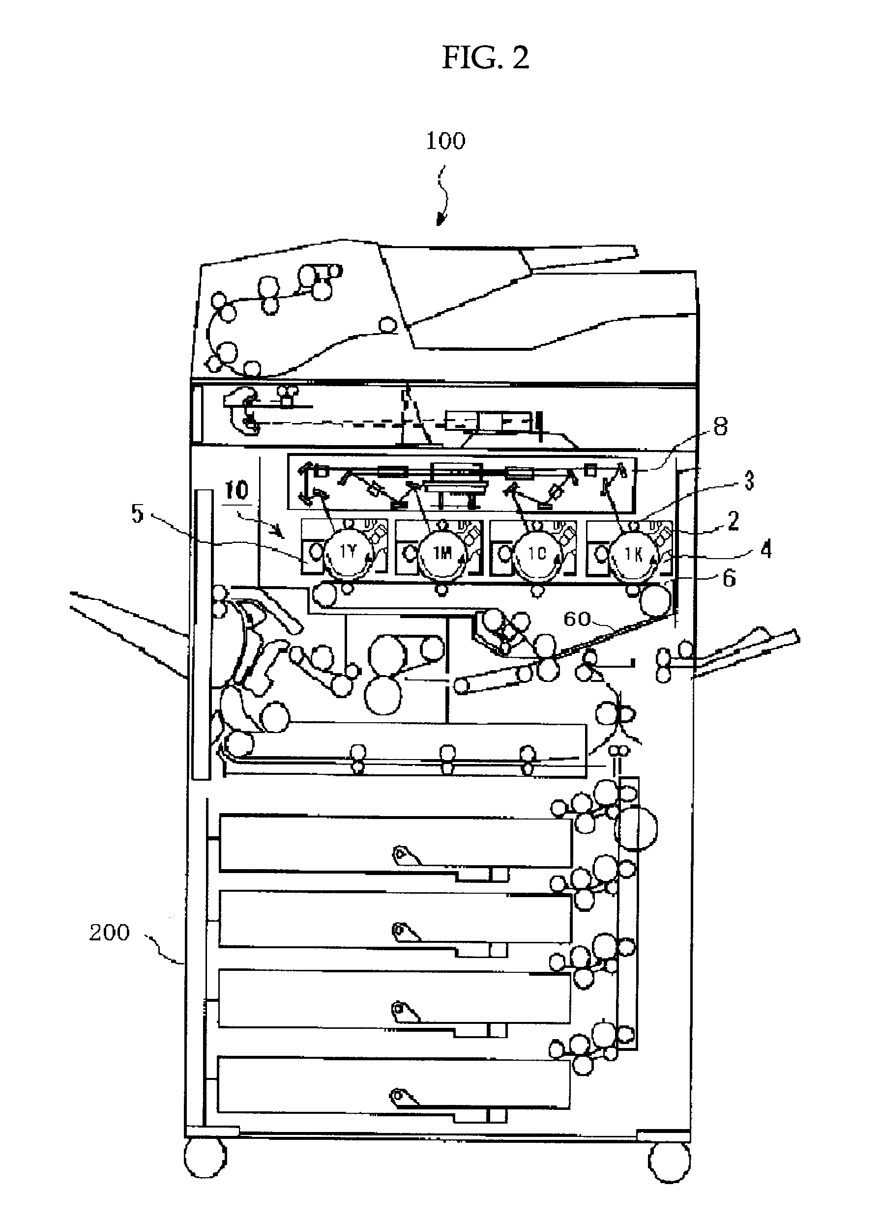
[0333]The process cartridge thus configured was attached to an image forming apparatus (Color MFP imagio Neo C600, manufactured by Ricoh Company, Ltd.) modified so that the process cartridge can be attached, and a continuous image output test outputting 100,000 sheets of A4 size paper having 6% of image / ...

examples 28 to 52

[0358]Evaluations were conducted under the same conditions as those of Example 27 except image bearing member protecting agents 2 to 26 were used instead of the image bearing member protecting agent 1 of Example 27.

[0359]The evaluation results of each image quality are shown in Table 5 to Table 10, and the observation results of the degradation condition for each member are shown in Table 11.

[0360]Moreover, the image forming apparatus of Example 28 was successively used for another continuous image output test outputting 400,000 more sheets (totaled 500,000 sheets including the sheets outputted in the previous test), the effect on images was not recognized, and almost no deterioration of the image bearing member, the cleaning member and the charge member was recognized.


PUM

PropertyMeasurementUnit
Temperatureaaaaaaaaaa

Abstract

To provide an image bearing member protecting agent that includes at least a hydrophobic organic compound and an amphiphile organic compound. Preferred embodiments are that the hydrophobic organic compound is a hydrocarbon wax, and the hydrocarbon wax is at least a wax selected from normal paraffins, isoparaffins, and cycloparaffins; and that the amphiphile organic compound is an polyalcohol esterified compound including a nonionic surface active surfactant, and the nonionic surface active surfactant is an alkyl carboxylic acid represented by a structural formula, CnH2n+1COOH.

Description

BACKGROUND OF THE INVENTION[0001]1. Field of the Invention[0002]The present invention relates to an image bearing member protecting agent for protecting a surface of an image bearing member which is used for forming electrophotographic images, a production method for the image bearing member protecting agent, a protection layer forming apparatus for forming a protection layer on the surface of the image bearing member using the image bearing member protecting agent, an image forming method, an image forming apparatus, and a process cartridge.[0003]2. Description of the Related Art[0004]Traditionally, electrophotographic image forming forms a visible image by having charged toner adhere to a static-charged latent electric field image formed with a static charge and formed on an image bearing member which has a photoconductive layer containing photoconductive substances thereon. The visible image is then transferred onto a recording media such as paper, and given heat, pressure, or so...

Claims


Application Information

Patent Timeline
IPC IPC(8): G03G5/147
CPCG03G5/14708G03G8/00G03G5/14721
Inventor YAMASHITA, MASAHIDENAKAI, HIROSHIYURA, JUNIIO, MASATOTANAKA, SHINYA
Owner RICOH KK
Why Eureka
Try Eureka