
Dynamic spinal implants incorporating cartilage bearing graft material

a cartilage bearing and spinal implant technology, applied in spinal implants, prostheses, medical science, etc., can solve the problems of inability to cope with degenerative disc disease, annulus and facet joints are not very effective at absorbing compression and shear force, etc., to eliminate the potential for dislocation and/or excessive translation

Inactive Publication Date: 2007-09-27
BIOMET MFG CORP
View PDF49 Cites 97 Cited by
  • Summary
  • Abstract
  • Description
  • Claims
  • Application Information

AI Technical Summary

Benefits of technology

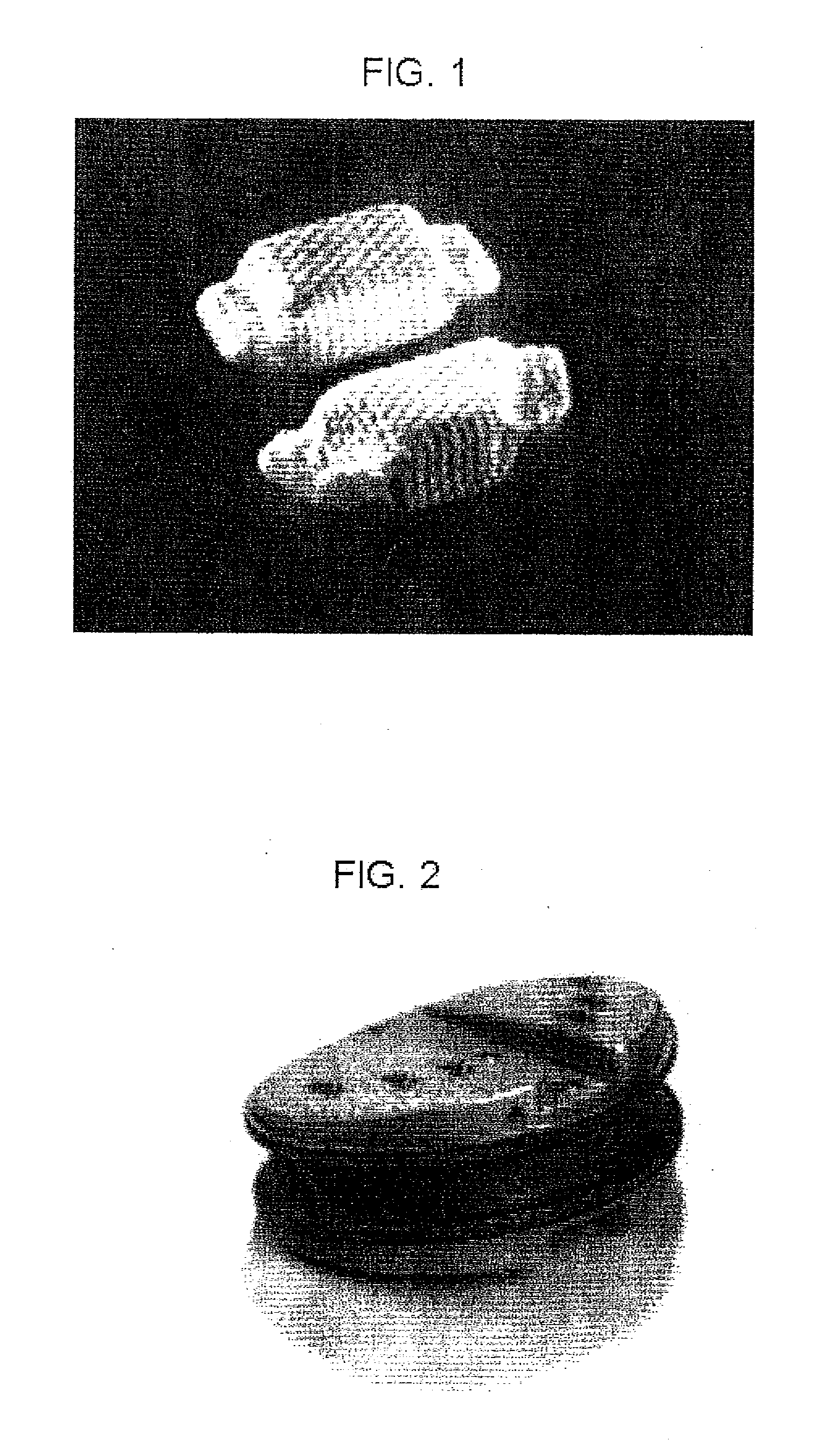
[0014] In one embodiment, a generally cylindrically shaped section is taken from both the femoral head and acetabulum (and / or pelvis) of a donor to form the cartilage bearing graft material. Preferably, the teres ligament and / or its attachments to the acetabulum and / or femur may be preserved (and / or separated and subsequently re-fixed or re-attached to bone) to serve as a constraint feature of this embodiment to mitigate or eliminate the potential for dislocation and / or excessive translation and / or rotation of these embodiments of the present invention. While this embodiment utilizes a hip joint as the donor joint, it will be understood that other joints may also be used in conjunction with the methods and apparatus of the present invention, including the knee, hip, ankle, vertebra, wrist, elbow or shoulder.
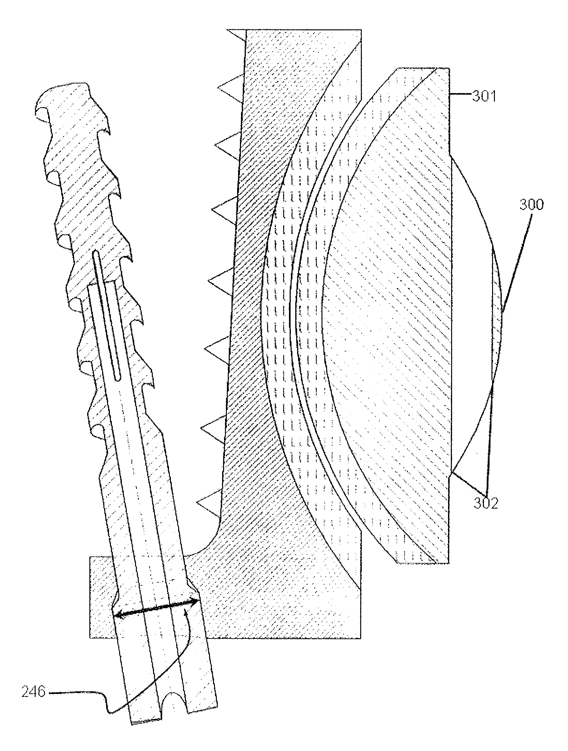
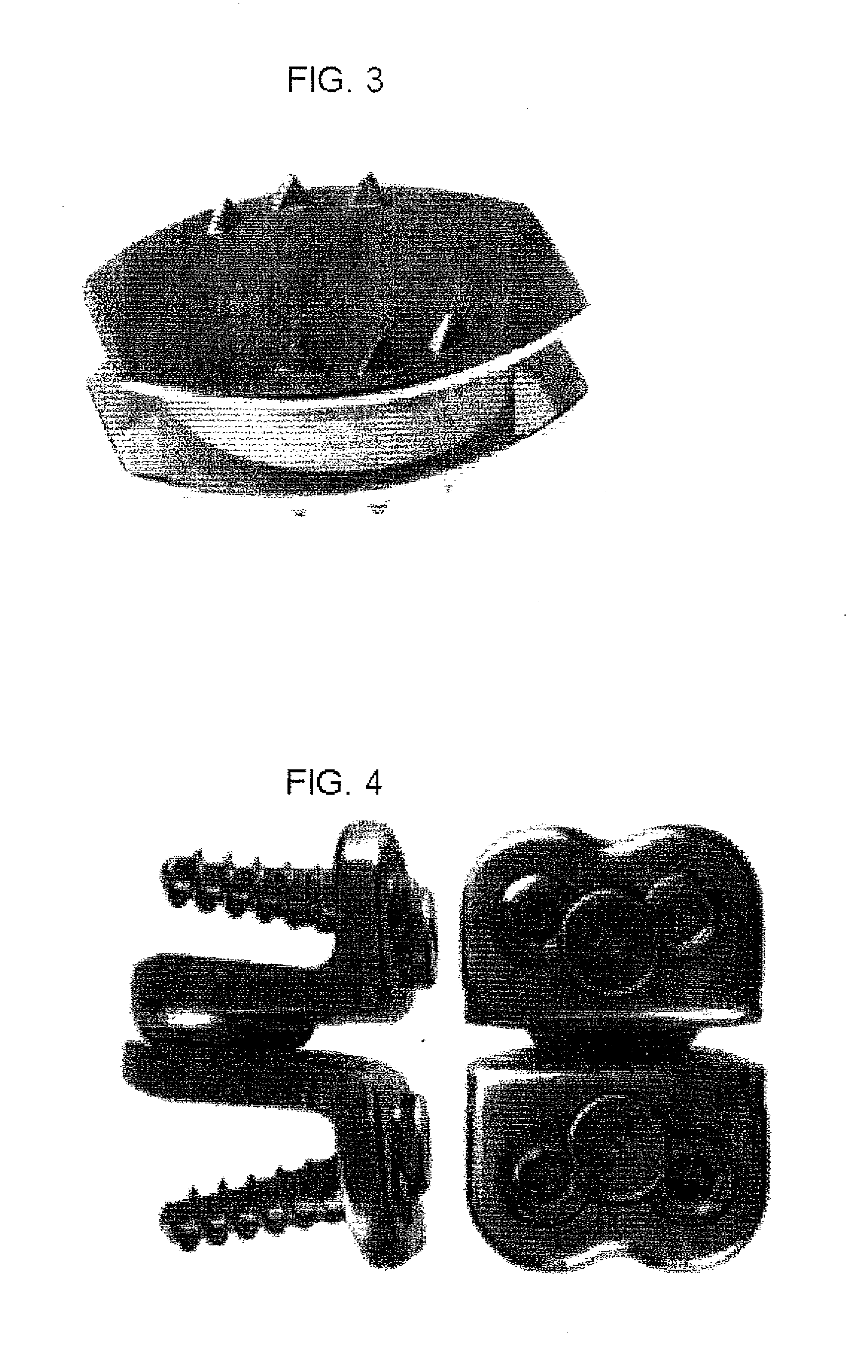
[0015] In another embodiment, the biological dynamic spinal implant with articular cartilage includes a keying feature that may be generally seated against the anterior cortex of the vertebral body or within an aperture or opening formed in the anterior cortex of the anterior corpus of the vertebral body. This keying feature preferably allows for the inclusion and additional fixation by a secondary fixation element. Preferably, the biological dynamic spinal implant is provided with textured features on one or more of the exterior surfaces opposite the cartilage bearing bone surface for mitigation of migration, subsidence, expulsion, and / or micromotion of the implant.

Problems solved by technology

However, the annulus is not very effective in withstanding compression and shear forces.
This degeneration of the intervertebral discs may lead to degenerative disc disease.
The annulus and facet joints are not capable of withstanding the applied compression and torsional loads, and as such, they gradually deteriorate.
As the annulus loses stability it tends to bow out and may develop a tear allowing nuclear material to extrude.
These breakdown products stimulate sensitive nerve endings in and around the disc, producing low back pain and sometimes, sciatica.
Affected individuals experience muscle spasms, reduced flexibility of the low back, and pain when ordinary movements of the trunk are attempted.
Even in the cases where re-stabilization occurs, the process can take many years and patients often continue to experience disabling pain.
While spinal fusion treatment is effective at relieving back pain, all discal motion is lost in the fused spinal motion segment.
The loss of motion in the affected spinal segment necessarily limits the overall spinal mobility of the patient.
Ultimately, the spinal fusion places greater stress on the discs adjacent the fused segment as these segments attempt to compensate for lack of motion in the fused segment, often leading to early degeneration of these adjacent spinal segments.
Although prosthetic devices have provided significant advances in the treatment of degenerative disc disease, almost all of these prosthetic devices suffer from the challenges of being non-biological devices.

Method used


Image

  • Dynamic spinal implants incorporating cartilage bearing graft material
  • Dynamic spinal implants incorporating cartilage bearing graft material
  • Dynamic spinal implants incorporating cartilage bearing graft material

Examples


Embodiment Construction

[0021] The intervertebral disc constitutes a major component of the functional spinal unit. Aging results in deterioration of the biological and mechanical integrity of the intervertebral discs. Disc degeneration may produce pain directly or perturb the functional spinal unit in such a way as to produce a number of painful entities. Whether through direct or indirect pathways, intervertebral disc degeneration is a leading cause of pain and disability in adults. Approximately 80% of Americans experience at least a single episode of significant back pain in their lifetime, and for many individuals, spinal disorders become a lifelong malady. The morbidity associated with disc degeneration and its spectrum of associated spinal disorders is responsible for significant economic and social costs. The treatment of this disease entity in the United States is estimated to exceed $60 billion annually in health care costs. The indirect economic losses associated with lost wages and decreased pr...


PUM


Abstract

A dynamic spinal implant utilizes cartilage bearing graft material in dynamic disc replacement and / or facet arthroplasty. Methods and apparatus for dynamic spinal implants incorporate bulk articular graft tissues derived from donor joint sources in human (allograft or autograft) or non-human (xenograft) tissue. The donor joint is preferably prepared as a biological dynamic spinal implant with articular cartilage as a bearing interface between adjacent bone surfaces that naturally articulate with respect to one another.

Description

RELATED APPLICATION [0001] The present application claims priority to U.S. Provisional Application Ser. No. 60 / 761,540, entitled “DYNAMIC SPINAL IMPLANTS INCORPORATING CARTILAGE BEARING GRAFT MATERIAL,” filed Jan. 24, 2006, the disclosure of which is hereby incorporated by reference.FIELD OF THE INVENTION [0002] The invention relates generally to methods and apparatus for the treatment of degenerative disc disease and associated conditions. More particularly, the present invention relates to the use of cartilage bearing graft material (allograft, autograft or xenograft) in dynamic disc replacement and / or facet arthroplasty. BACKGROUND OF THE INVENTION [0003] The spinal motion segment consists of a unit of spinal anatomy bounded by two vertebral bodies, including the two vertebral bodies, the interposed intervertebral disc, as well as the attached ligaments, muscles, and the facet joints. The disc consists of the end plates at the top and bottom of the vertebral bones, the soft inner...

Claims


Application Information

Patent Timeline
IPC IPC(8): A61F2/44
CPCA61B17/86A61F2310/00359A61B17/8625A61B17/864A61F2/28A61F2/4405A61F2/4425A61F2002/2835A61F2002/3021A61F2002/30245A61F2002/30495A61F2002/30578A61F2002/30583A61F2002/30772A61F2002/30841A61F2002/30878A61F2002/30904A61F2002/30909A61F2002/4631A61F2002/4649A61F2210/0085A61F2220/0025A61F2230/0067A61F2230/0071A61F2002/4475A61B17/861A61F2002/30593
Inventor HAINES, TIMOTHY
Owner BIOMET MFG CORP
Learn More