Intake structure for seat type vehicle

a seat type, air intake technology, applied in the direction of machines/engines, jet propulsion mounting, combustion air/fuel air treatment, etc., can solve the problems of increasing the length of the air intake path and the inability to construct, and achieve the effect of shortening the air intake path

Active Publication Date: 2007-10-04
HONDA MOTOR CO LTD
View PDF23 Cites 34 Cited by
  • Summary
  • Abstract
  • Description
  • Claims
  • Application Information

AI Technical Summary

Benefits of technology

[0007]The present invention has been made in view of the above-mentioned circumstances. It is an object of an embodiment of the present invention to provide an inta...

Problems solved by technology

However, the construction in which the intake port is provided in an upper portion of the hollow frame leads to an increa...

Method used


Image

  • Intake structure for seat type vehicle
  • Intake structure for seat type vehicle
  • Intake structure for seat type vehicle

Examples


Embodiment Construction

[0026]An intake structure for a seat type vehicle according to an embodiment of the present invention will now be described with reference to the drawings.

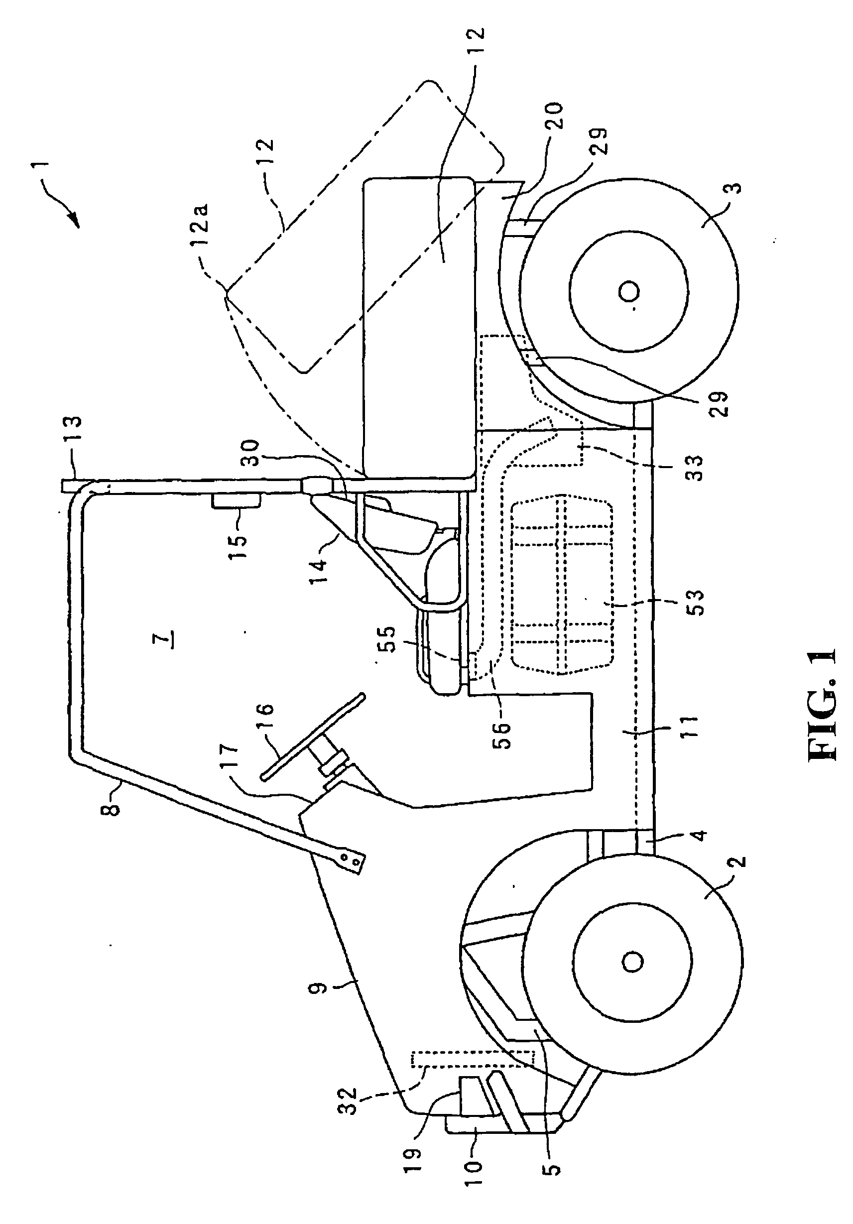
[0027]It should be noted that in this embodiment, a MUV (Multi Utility Vehicle) will be described as an example of the seat type vehicle. Further, in the following description, as for the up, down, front, and rear directions, the front side refers to the left-hand side as seen in FIG. 1, and the left and right directions refer to the directions as seen from the driver when seated in the occupant seat.

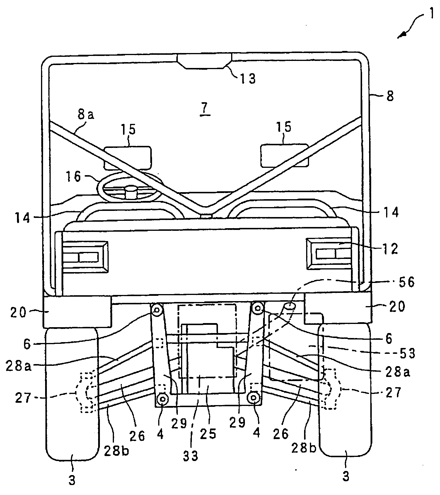
[0028]As shown in FIG. 1, a MUV vehicle 1 is a four-wheel vehicle capable of driving over rough terrain or the like and having two front wheels 2 and two rear wheels 3 provided on the front and rear sides, respectively.

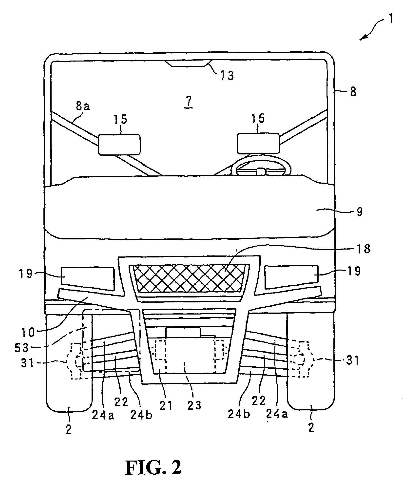
[0029]As shown in FIGS. 1 and 2, at the front portion of the vehicle 1, there are provided a bonnet 9 attached by means of a hinge or the like so as to freely open and close in the vertical direction, a front grille 18 ...


PUM


Abstract

To provide an intake structure for a seat type vehicle which makes it possible to shorten the air intake path and to prevent the taken-in air from being heated with the heat of an engine. An intake structure for a seat type vehicle is provided in which an engine and a fuel tank are mounted side by side in the lateral direction of the vehicle under the occupant seats attached onto a frame. An air cleaner is arranged to the rear of the engine with an intake port for the air cleaner being provided under the occupant seats and above the fuel tank.

Description

CROSS-REFERENCE TO RELATED APPLICATIONS[0001]The present application claims priority under 35 USC 119 to Japanese Patent Application No. 2006-096581 filed on Mar. 31, 2006 the entire contents of which are hereby incorporated by reference.BACKGROUND OF THE INVENTION[0002]1. Field of the Invention[0003]The present invention relates to an intake structure for a seat type vehicle for sucking the air to be taken into an engine.[0004]2. Description of Background Art[0005]A MUV (Multi Utility Vehicle) vehicle is commonly known as a seat type vehicle capable of driving over rough terrain or the like. In the vehicle of this type, an engine and an air cleaner are mounted below a driver's seat, and a hollow frame (roll bar) that extends in the vertical direction of the vehicle is provided so as to surround the driver's seat. The air to be supplied to this engine is taken in from an intake port provided in an upper portion of the hollow frame. The air thus taken in passes through the hollow of ...

Claims


Application Information

Patent Timeline
IPC IPC(8): B60K13/02F02M35/02
CPCB60K13/02F02M35/162F02M35/02
Inventor NOZAKI, NAOKIKOBAYASHI, TAKESHIINOUE, MASAHIROKANAI, KATSUMI
Owner HONDA MOTOR CO LTD
Why Eureka
Try Eureka