Light source

a light source and light source technology, applied in the field of light sources, can solve the problems of mirror deterioration fast, difficult to capture debris particles scattering from the plasma at high speed, damage to the film of the multi-layer mirror,

Inactive Publication Date: 2007-10-04
CANON KK
View PDF9 Cites 15 Cited by
  • Summary
  • Abstract
  • Description
  • Claims
  • Application Information

AI Technical Summary

Benefits of technology

[0011]At least one exemplary embodiment of the present invention is directed to a light source in which debris particles produced from plasma can be prevented from reaching a mirror.

Problems solved by technology

Debris particles adhere to or collide with the multilayer mirror, and damage of films of the multilayer mirror.
However, in the above-described debris-particle eliminating method, it is difficult to capture debris particles scattering from the plasma at high speed unless a considerably strong magnetic field is applied.
Conversely, when the strength of the magnetic field is decreased, debris particles easily reach the mirror, and the mirror deteriorates fast.

Method used


Image

  • Light source
  • Light source
  • Light source

Examples


first exemplary embodiment

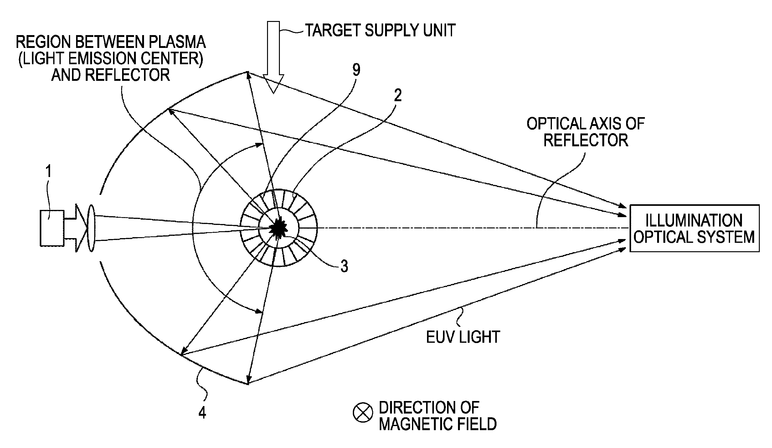
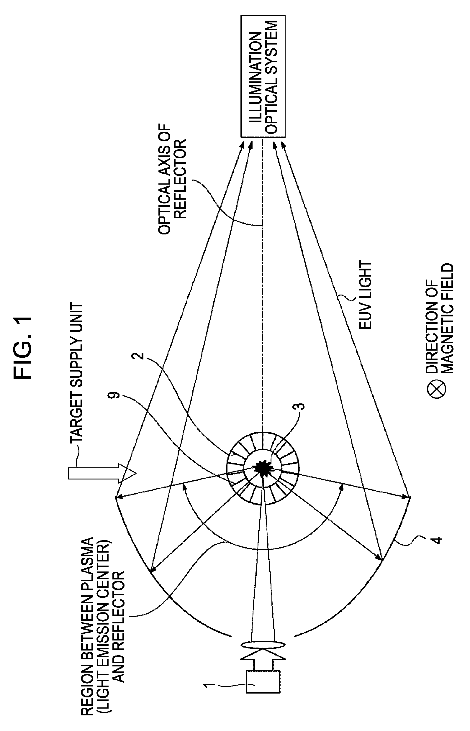
[0034]FIG. 1 is a schematic view of a LPP light source according to a first exemplary embodiment of the present invention. In the first exemplary embodiment a magnetic field is applied by a magnetic-field generator to a space where a debris filter is placed, as shown in FIG. 1. While a magnetic field is applied from the front side of the paper of FIG. 1 to the back side in the exemplary embodiment, it can be applied in an opposite direction. The LPP light source will be described in detail below.

[0035]The LPP light source includes a laser source 1, such as a YAG laser, a debris filter 2, plasma 3 (a light emitting point of EUV light), and a reflector (multilayer mirror) 4. Laser light is applied from the laser source 1 to a target (e.g., xenon or tin) supplied by a target supply unit, thereby generating plasma. That is, the laser source 1 and the target supply unit constitute a plasma generator.

[0036]EUV light emitted from the plasma is reflected by the reflector 4, and is guided to...

second exemplary embodiment

[0065]A second exemplary embodiment of the present invention will now be described with reference to FIGS. 4A and 4B.

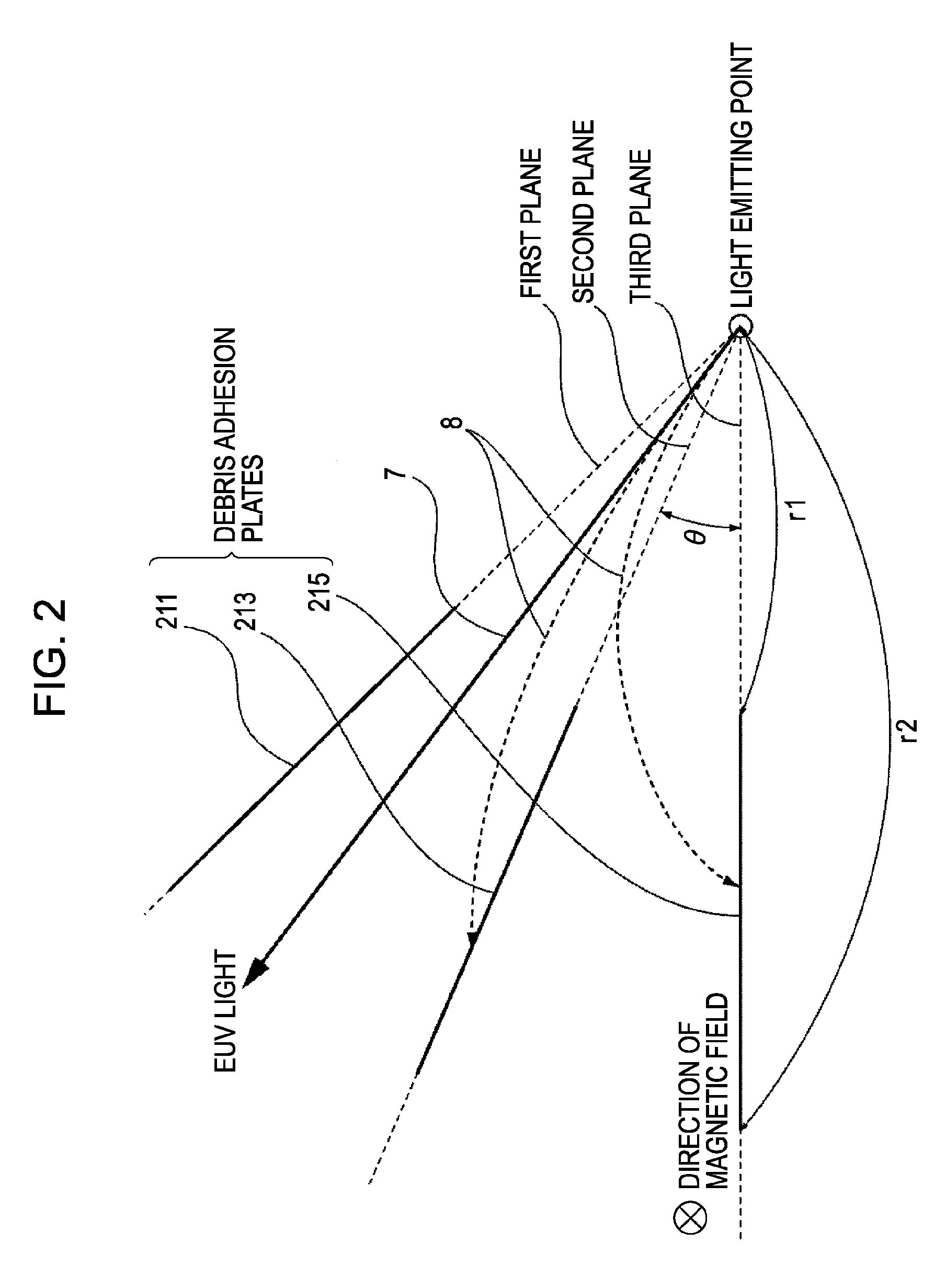
[0066]According to the condition (2) adopted in the first exemplary embodiment, it is satisfactory as long as each debris adhesion plate is substantially parallel to the magnetic line of force passing through the debris adhesion plate. Therefore, for example, the debris adhesion plates can be arranged in a manner shown in FIGS. 4A and 4B. FIG. 4A is a cross-sectional view of a debris filter 2, taken along a plane including the optical axis of a reflector, and FIG. 4B is a cross-sectional view of the debris filter 2, taken perpendicularly to the optical axis of the reflector and viewed from the light-emitting-point side. As shown in FIG. 4B, magnets are arranged so that magnetic lines of force extend radially in a region where the debris filter 2 is provided. That is, one permanent magnet is disposed on the optical axis of the reflector, and other permanent magnets are...


PUM


Abstract

At least one exemplary embodiment is directed to a light source which includes a plasma generator configured to generate plasma, a mirror configured to reflect light that is produced by the plasma, a plurality of plates provided between the plasma and the mirror and arranged radially around an axis passing through a light emission center, and a magnetic-field generator for generating a magnetic line of force between the plasma and the mirror so that trajectories of charged particles scattering from the plasma are curved toward the plates.

Description

BACKGROUND OF THE INVENTION[0001]1. Field of the Invention[0002]The present invention relates to a light source, and more particularly though not exclusively, to a light source that emits EUV (extreme ultraviolet) light.[0003]2. Description of the Related Art[0004]In recent semiconductor manufacturing apparatuses, the wavelength of light emitted from a light source has been shortened, and exposure apparatuses using EUV light have attracted attention as next-generation exposure apparatuses.[0005]A laser produced plasma (LPP) light source is typical of EUV light sources used in EUV exposure apparatuses. FIG. 10 is a schematic view of the LPP light source. In this light source, high-intensity laser light (normally having a repetition frequency of several kilohertz) is applied to a target material, such as xenon, thereby producing high-temperature plasma. From the plasma, EUV light having a wavelength of approximately 13 nm is radiated. The radiated EUV light is reflected by a multilaye...

Claims


Application Information

Patent Timeline
Patent Type & Authority Applications(United States)
IPC IPC(8): G01J3/10H05G2/00
CPCB82Y10/00G03F7/70033H05G2/005H05G2/003H05G2/008G03F7/70916H01J65/00H01J61/02H01J35/02
Inventor FUJIMOTO, KAZUKI
Owner CANON KK
Why Eureka
Try Eureka