

Apparatus and method for exposing a substrate to UV radiation using a reflector having both elliptical and parabolic reflective sections
a technology of reflector and substrate, which is applied in the direction of lighting and heating apparatus, therapy, furnaces, etc., can solve the problems of consuming significant processing time, affecting the overall fabrication process, and affecting the effect of light loss
- Summary
- Abstract
- Description
- Claims
- Application Information
AI Technical Summary
Benefits of technology
Problems solved by technology
Method used
Image


Examples
Embodiment Construction
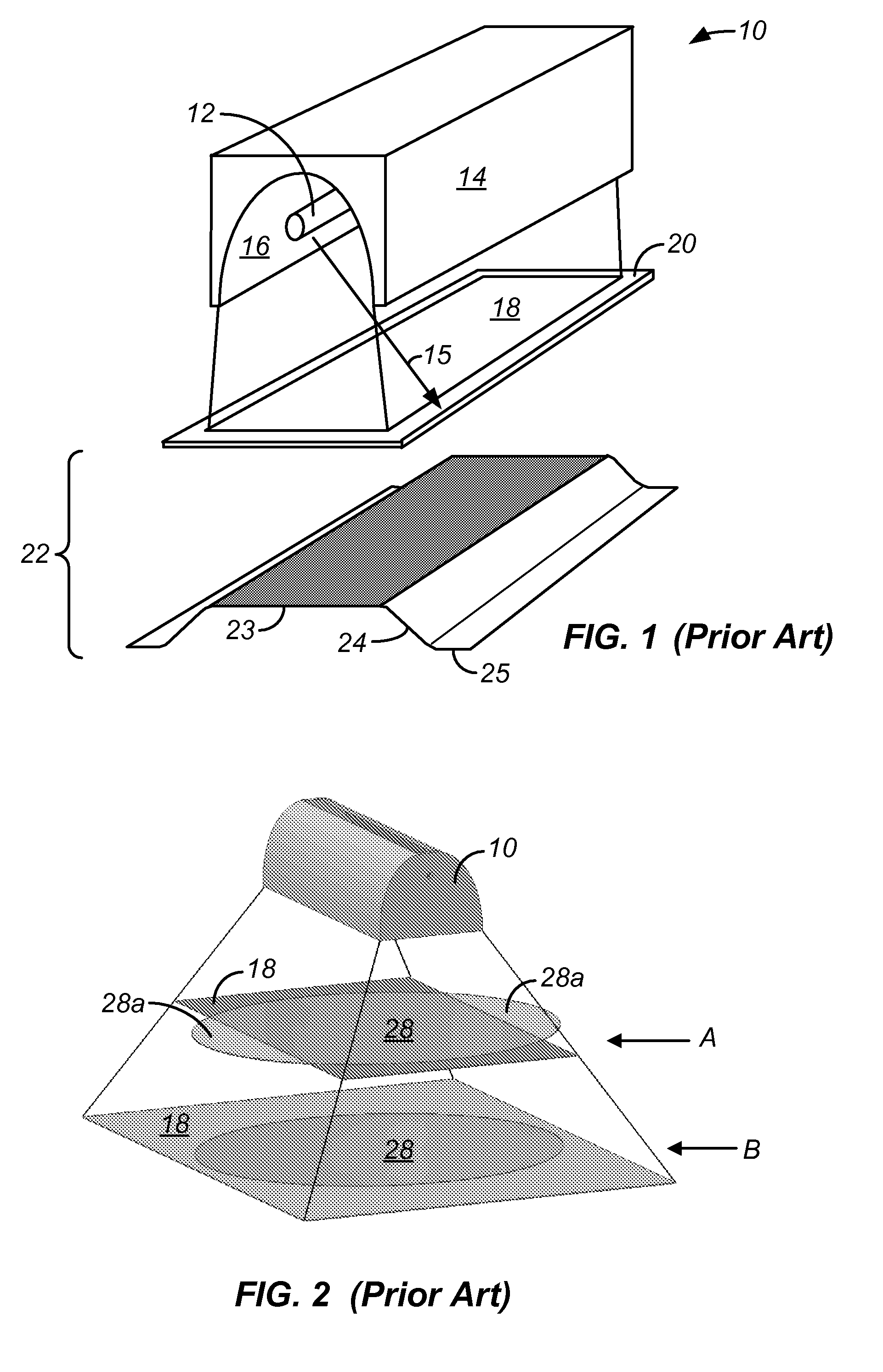
[0047]FIG. 1 is a perspective view of a prior art microwave UV lamp 10 that illustratively depicts an irradiance level of radiation generated by the lamp over a substantially rectangular exposure area. Lamp 10 includes an elongated UV bulb 12 mounted within a housing 14. Housing 14 includes a reflector 16 that faces UV bulb 12 and directs UV radiation into a flood pattern 18 over a substrate 20. Reflector 16 is placed inside a resonant cavity, which limits the size and shape of the reflector.
[0048] While reflector 16 reflects the majority of radiation (within selected wavelengths) that strikes its surface within flood pattern 18, some radiation escapes the reflector surface and falls outside the boundaries of pattern 18. An example of such radiation is illustrated in FIG. 1 by radiation path 15. The intensity of radiation generated by lamp 10 both within and outside flood pattern 18 is illustrated conceptually (in a simplified manner) in bottom portion 22 of FIG. 1. As shown in bot...
PUM
| Property | Measurement | Unit |
|---|---|---|
| thickness | aaaaa | aaaaa |
| dielectric constant | aaaaa | aaaaa |
| temperature | aaaaa | aaaaa |
Abstract
Description
Claims
Application Information