

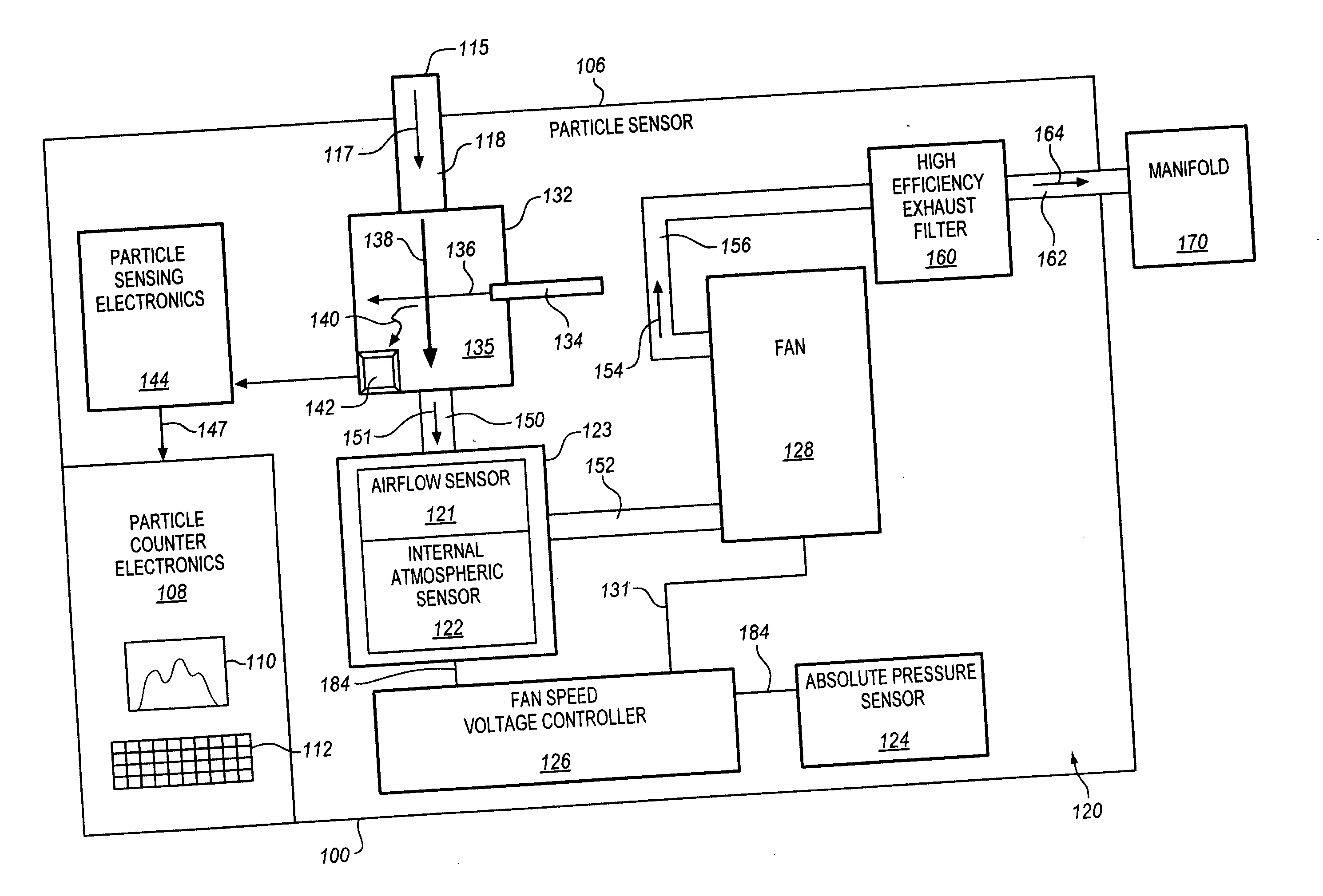
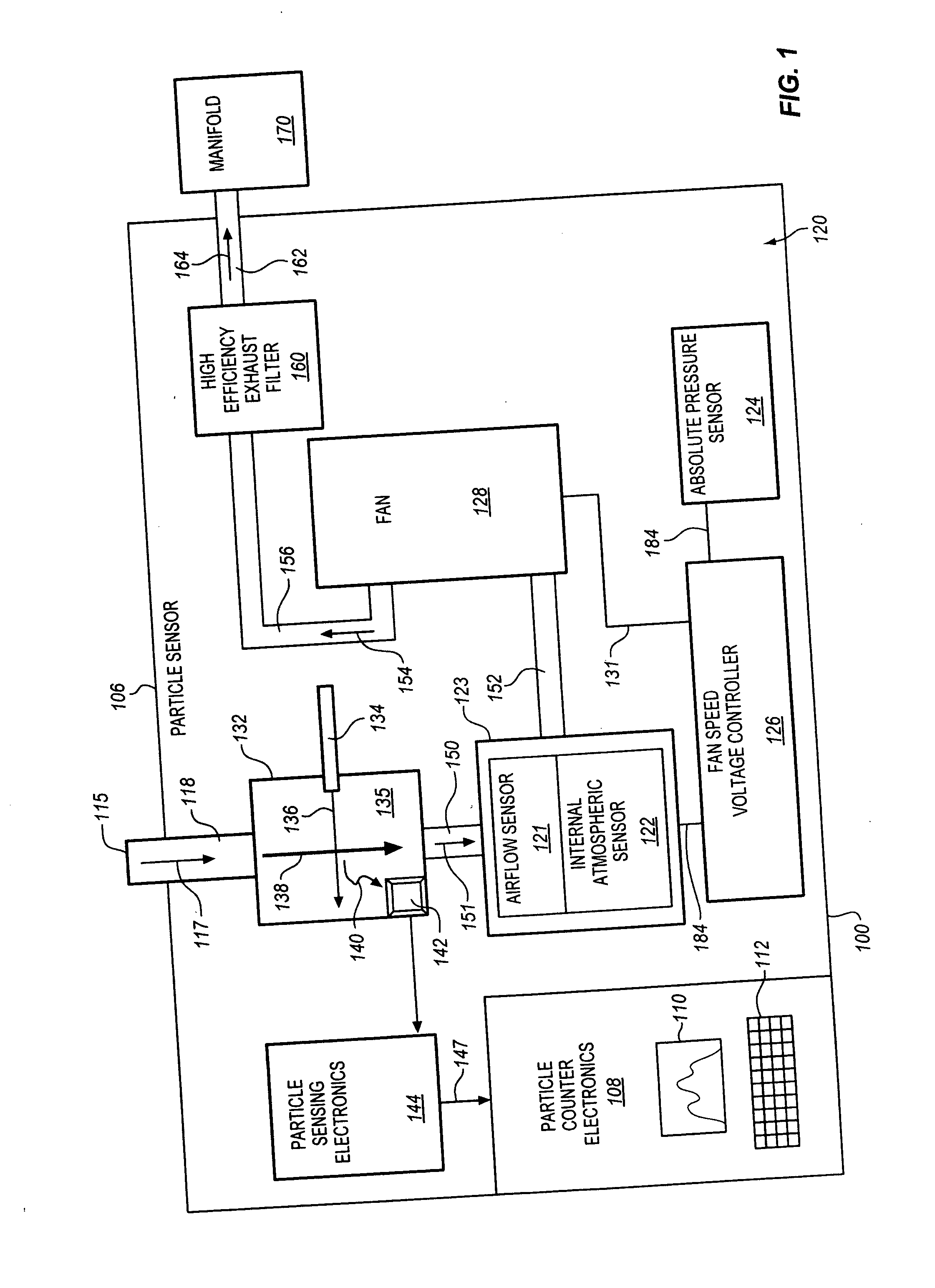
Aerosol particle sensor with axial fan
a technology of axial fan and optical particle sensor, which is applied in the field of airflow system, can solve the problems of large number of particle counters, inability to monitor all sample locations in real time, and loss of large particles down the required long sample tubing run, so as to reduce the cost, size and power consumption of optical particle counters, and simplify the whole plant particle counter system
- Summary
- Abstract
- Description
- Claims
- Application Information
AI Technical Summary
Benefits of technology
Problems solved by technology
Method used
Image

Examples
Embodiment Construction
[0024] In this disclosure, the term “light” is not limited to visible radiation but is used in a broad sense meaning any electromagnetic radiation, including infrared, ultraviolet, extreme ultraviolet, and x-ray radiation. It should be noted that particle sensors and particle counters as disclosed herein are designed to be able to detect single particles which are unconstrained in a flowing gas as distinguished from other systems that detect and analyze the particles of the gas itself, clouds of particles suspended in a gas, or particles which are constrained in the gas, such as constrained to flow in a single line past a light beam. Those skilled in the art recognize that it is a much more difficult task to detect and size single particles flowing unconstrained in a gas, particularly particles of less than one micron in size; therefore, the art of particle counting involves different technology than these other particle detection and analysis systems.
[0025] An aerosol particle cou...
PUM
 Abstract
Description
Claims
Application Information