
Measurement method and apparatus, exposure apparatus

Inactive Publication Date: 2007-10-04
CANON KK
View PDF5 Cites 14 Cited by
  • Summary
  • Abstract
  • Description
  • Claims
  • Application Information

AI Technical Summary

Benefits of technology

[0012] The present invention is directed to a measurement method and apparatus that can precisely measure an optical characteristic of the optical system, such as a wavefront aberration.

Problems solved by technology

However, the conventional measurement apparatus cannot precisely measure the wavefront aberration of the projection optical system.
However, a shift occurs between the design value and the actual value due to manufacturing errors of the apparatus, such as a telecentric difference for each image point of the projection optical system, a manufacture error of a plate, and an arrangement error of the light receiving element.
When the design value is used for a process parameter, a precise image conversion process cannot be performed, and calculated wavefront aberration information contains a measurement error.
Moreover, even when an image conversion process is performed using for a process parameter a design value that has no shift from an actual value, the wavefront aberration information contains a measurement error, because a manufacturing error of the apparatus cannot be eliminated, such as inclinations among a bottom plane of the projection optical system, a plate plane, and an inclination of a light receiving plane.
This problem is not limited to the LDI type measurement apparatus, but other measurement apparatuses that measure as two-dimensional information an optical characteristic of an optical system, such as a PDI type measurement apparatus and a LSI type measurement apparatus.

Method used


Image

  • Measurement method and apparatus, exposure apparatus
  • Measurement method and apparatus, exposure apparatus
  • Measurement method and apparatus, exposure apparatus

Examples


Embodiment Construction

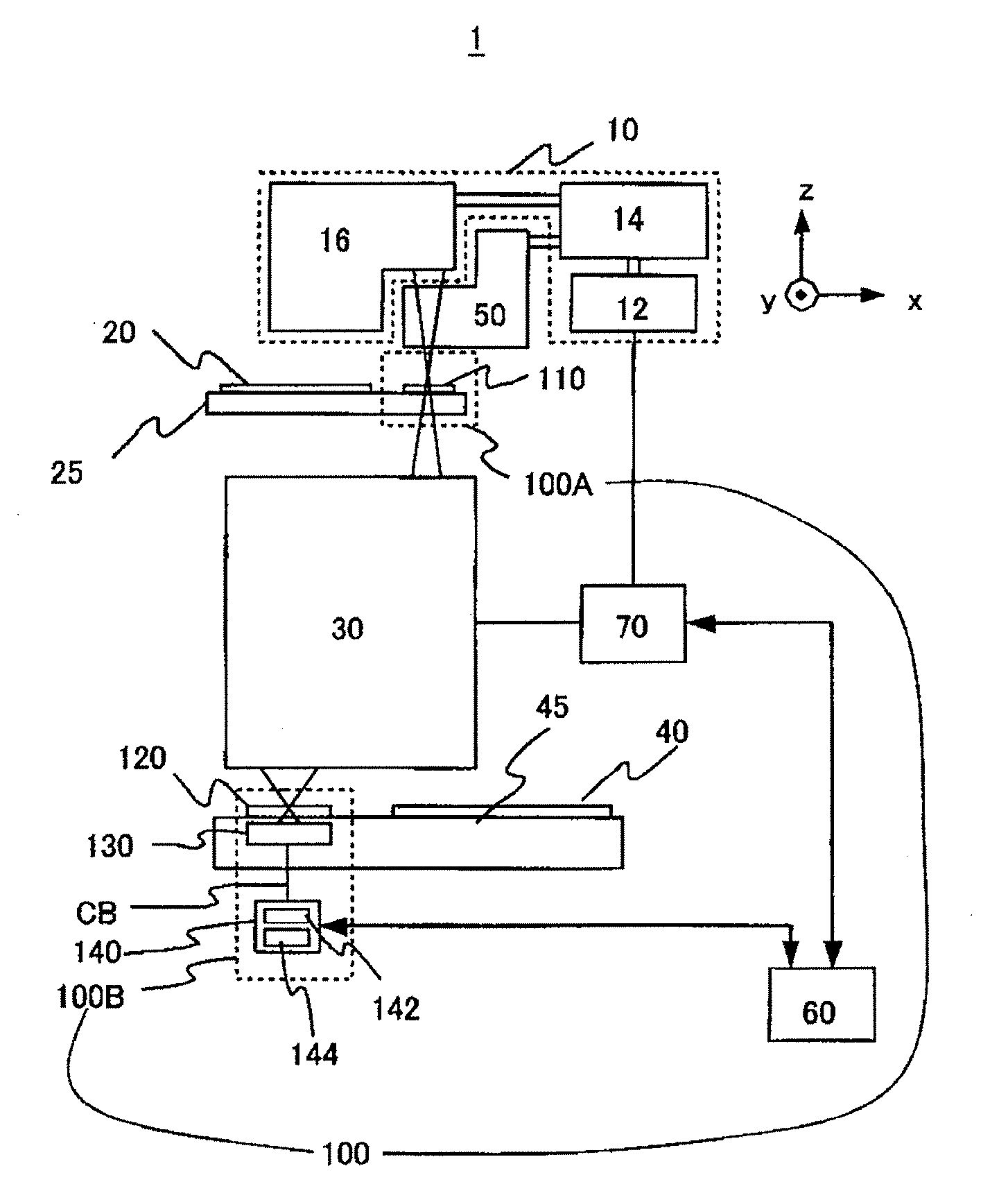
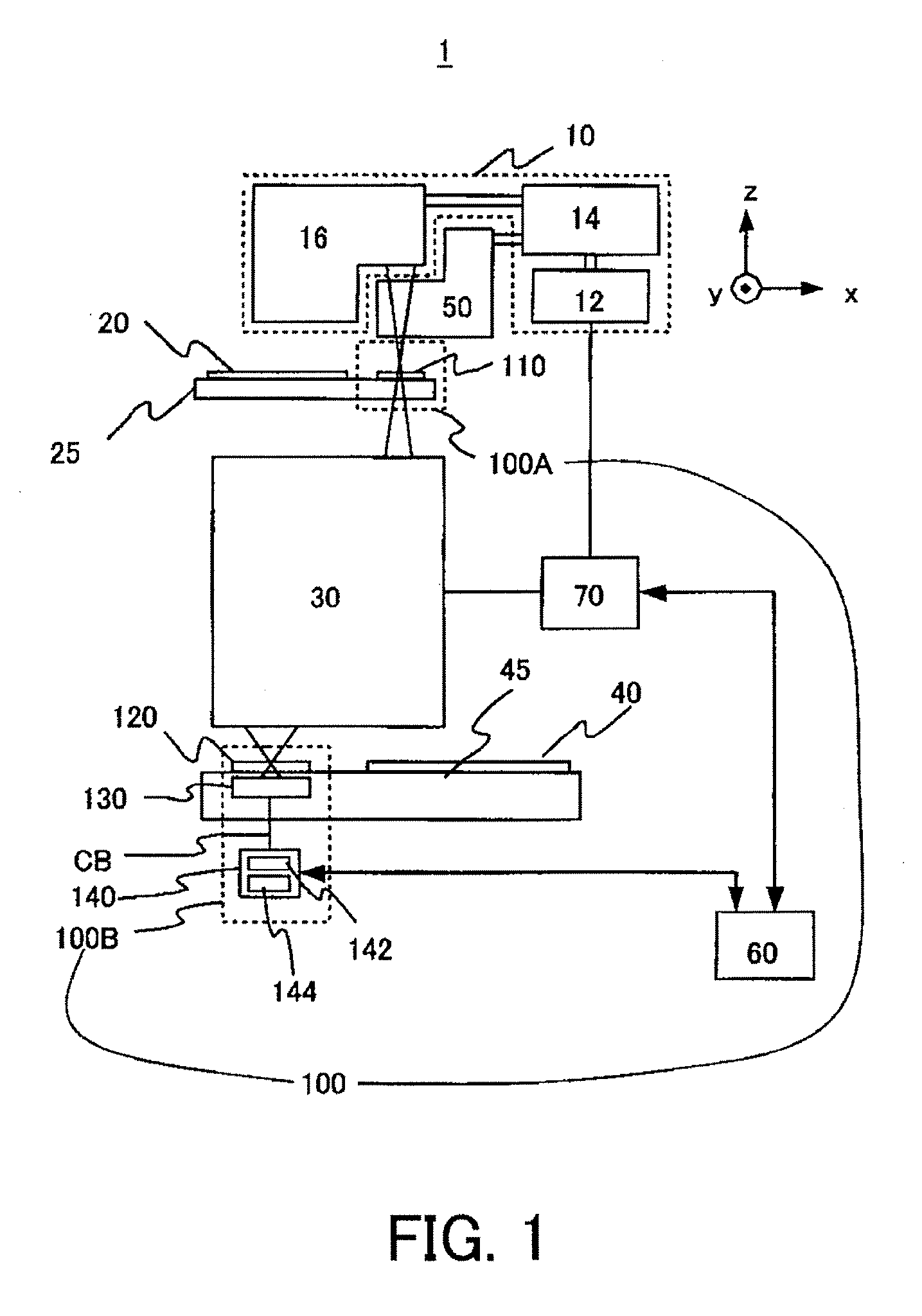
[0028] This inventor has discovered that in order to precisely measure a wavefront aberration, it is necessary to calculate or measure a wavefront aberration using an actual value for a process parameter rather than the design value, and to correct the wavefront aberration. This correction needs to use, for example, a parameter (linearity gain) used to correct an aberrational variance amount of a wavefront aberration measured by the measurement apparatus, and a parameter (absolute value) used to correct the aberration of the member in the measurement apparatus other than the target optical system. The following description refers to a parameter as an “offset parameter” to be reflected on the wavefront aberration measured by the measurement apparatus. A “system parameter” is a generic term of the “process parameter” and the “offset parameter.”

[0029] A fundamental principle of the inventive measurement apparatus and method reflects a manufacturing error on the “process parameter” as a...


PUM


Abstract

A measurement method for measuring a wavefront aberration of a target optical system using a measurement apparatus that measures the wavefront aberration of the target optical system by detecting an interference pattern includes the steps of measuring as a system parameter a shift from a design value of a value that defines a structure of the measurement apparatus and the target optical system, and measuring the wavefront aberration of the target optical system using the system parameter.

Description

BACKGROUND OF THE INVENTION [0001] The present invention relates to a measurement method and apparatus. [0002] A conventional projection exposure apparatus projects a circuit pattern of a reticle onto a photosensitive substrate, such as a wafer, via a projection optical system in manufacturing fine semiconductor devices, such as a semiconductor memory and a logic circuit, using the photolithography technology. [0003] Since a projection exposure apparatus is required to precisely transfer a reticle pattern onto a wafer at a predetermined magnification or reduction ratio, use of a projection optical system having an extremely restrained aberration or a superior imaging characteristic is important. In particular, along with the increasing demand for fine processing to semiconductor devices, a transfer pattern is sensitive to the aberration of an optical system. Therefore, there is a demand for a precise measurement of a optical characteristic, such as a wavefront aberration, of the pro...

Claims


Application Information

Patent Timeline
IPC IPC(8): G01B9/02
CPCG01J9/02G03F7/706G01M11/0271G01M11/0264G01B9/02024G01B11/2408G01D3/00H01L21/0274
Inventor YAMAMOTO, KAZUKI
Owner CANON KK
Learn More