Thin film device

a thin film coil and coil technology, applied in the field of thin film coils, can solve the problem of not being able to conclude that the thin film coils meet the requirements of performance improvement for high frequency use, and achieve the effect of increasing the direct current resistance of the thin film coils

Inactive Publication Date: 2007-10-04
TDK CORPARATION
View PDF8 Cites 2 Cited by
  • Summary
  • Abstract
  • Description
  • Claims
  • Application Information

AI Technical Summary

Benefits of technology

[0008]In view of the foregoing, it is desirable to provide a thin film device capable of improving the Q value when employing a thin film coil wound on a magnetic film.
[0012]In accordance with the thin film device of the present invention, in the thin film coil wound on the second magnetic film, the thickness of the first coil portions is larger than the thickness of the second portions. This enables the Q value to be improved than the case where the thickness of the first coil portions is equal to or less than that of the second coil portions. In this case, for example, by setting the ratio of the thickness TB of the second coil portions to the thickness TA of the first coil portions, namely TB / TA, to a range of 0.1<TB / TA<1, a sufficient Q value can be attained while suppressing an increase in the direct current resistance of the thin film coil.

Problems solved by technology

Although the thin film device of the related art having the thin film coil of solenoid type fulfills the requirements of miniaturization and low back, it cannot conclude that the thin film device fulfills the requirement of performance improvement for use in high frequency.

Method used


Image

  • Thin film device
  • Thin film device
  • Thin film device

Examples


examples

[0045]Examples of the present invention will be described below.

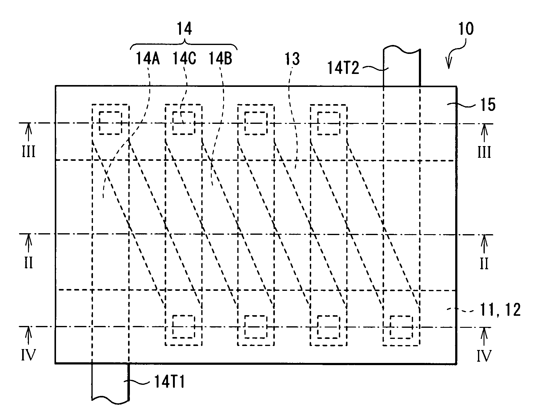
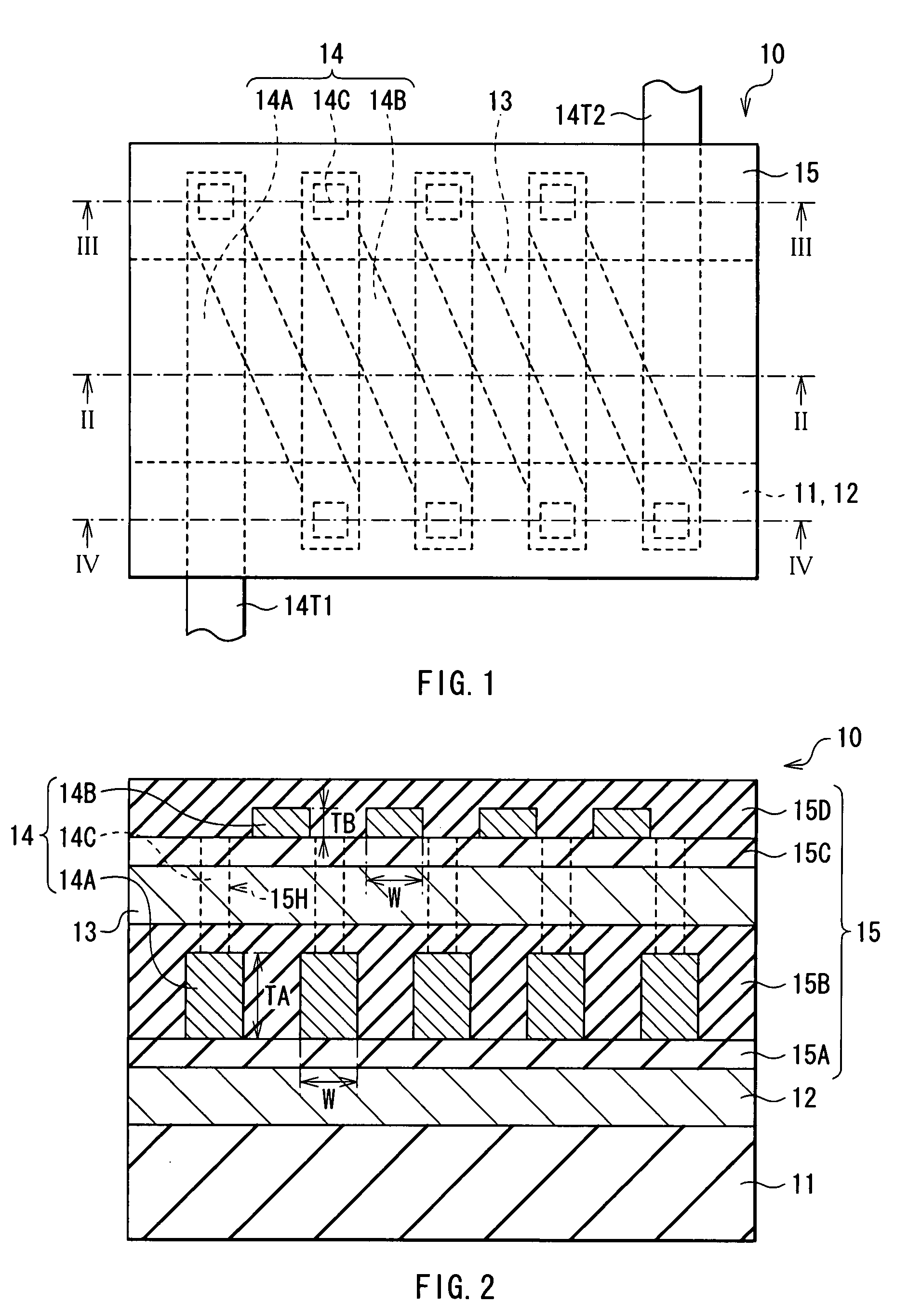
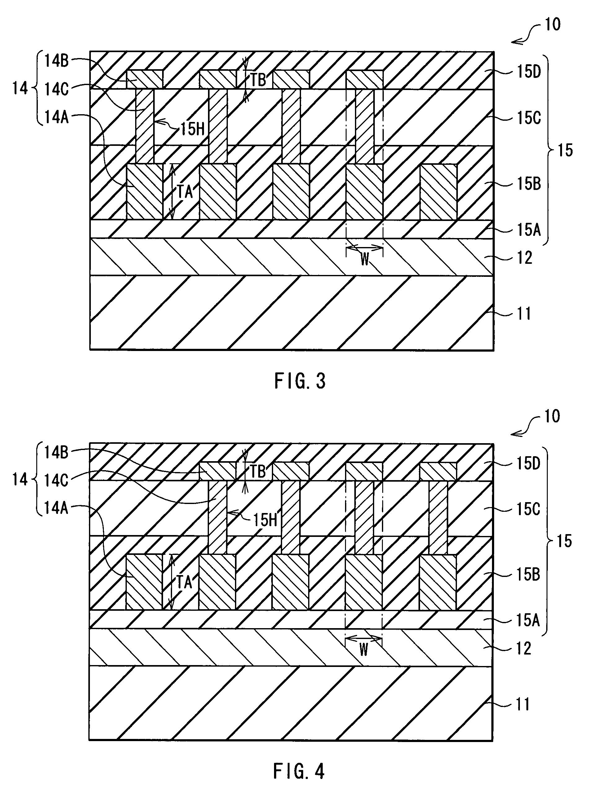
[0046]Various performances of the thin film inductors provided with the thin film coil of solenoid type as shown in FIGS. 1 to 6 were estimated by magnetic field analysis using finite element method. The results are shown in FIGS. 9 to 13. FIGS. 9 to 12 show inductance Ldc (×10−6H), inductance L1M (×10−6H), resistance Rdc (Ω), and thickness ratio TB / TA dependence of resistance R1M (Ω), respectively. FIG. 13 shows thickness ratio TB / TA dependence of A value Q1M (Ω). The above-mentioned “inductance Ldc” and “resistance Rdc” were values found from magnetostatic field analysis, and can generally be approximated with an analysis value in low frequency regions in the order of kHz. On the other hand, the above-mentioned “inductance L1M”, “resistance R1M” and “Q value Q1M” were values when the frequency is 1 MHz.

[0047]When estimating the various performances of the thin film inductors, a series of parameters were set as follows...


PUM

PropertyMeasurementUnit
frequencyaaaaaaaaaa
thickness TBaaaaaaaaaa

Abstract

A thin film device is provided which is capable of improving a Q value when employing a thin film coil wound on a magnetic film. In the thin film coil wound on an upper magnetic film, the thickness (TA) of lower coil portions in between a lower magnetic film and the upper magnetic film is larger than the thickness (TB) of upper coil portions not in between the lower and upper magnetic films (the thickness ratio TB / TA<1). The crossover magnetic flux crossing over the first coil portions in between the first and the second magnetic films can be reduced than the case where the thickness (TA) of the lower coil portions is equal to or less than the thickness (TB) of the upper coil portions (the thickness ratio TB / TA≧1).

Description

BACKGROUND OF THE INVENTION[0001]1. Field of the Invention[0002]The present invention relates to a thin film device having a thin film coil wound on a magnetic film.[0003]2. Description of the Related Art[0004]In the field of electronic equipments for various purposes, a thin film device with a thin film coil has been widely used in the recent years. As an example of the thin film device, there is a thin film inductor that is a circuit element having inductance.[0005]As the shape of a thin film coil mounted on a thin film device, spiral type has been employed to meet the requirements of miniaturization (reduction in the area of a device) and low back (reduction in the thickness of the device). On the other hand, solenoid type has been employed for the purposes where the performance improvement is also required in addition to miniaturization and low back (for example, refer to Japanese Unexamined Patent Publication No. 05-029146). In the thin film device having the thin film coil of ...

Claims


Application Information

Patent Timeline
Patent Type & Authority Applications(United States)
IPC IPC(8): G11B5/147G11B5/17
CPCG11B5/17H01F2017/0066H01F17/0013
Inventor FUJIWARA, TOSHIYASUCHOI, KYUNG-KU
Owner TDK CORPARATION
Why Eureka
Try Eureka