Charging device with off-center coil

a charging device and coil technology, applied in the field of neurostimulation treatment systems, can solve the problems of reducing the risks of heating the charging device, and achieve the effects of increasing the directionality of the magnetic field, reducing the sensitivity to the orientation of the charging device, and more robust coupling

Active Publication Date: 2020-09-17
AXONICS
View PDF0 Cites 0 Cited by
  • Summary
  • Abstract
  • Description
  • Claims
  • Application Information

AI Technical Summary

Benefits of technology

[0008]This mismatch of winding types between the charging device and the implantable pulse generator provides several benefits including the enabling of more robust coupling between the charging device and the implantable pulse generator when power is transmitted from the charging device to the implantable pulse generator. Specifically, the use of mismatched winding types can result in a robust coupling that is either insensitive to the orientation of the charging device with respect to the implantable pulse generator and/or that has reduced sensitivity to the orientation of the charging device with respect to the implantable pulse generator.
[0009]The core of the charging device can be positioned between the wire winding of the charging device and circuitry of the charging device. This circuitry of the charging device can, for example, control the generation of the magnetic field by the charging device. The core can be designed such that the magnetic field does not extend through the core towards the circuitry, but is rather, the magnetic field is directed in a desired direction. The positioning of the core can focus the magnetic field, and specifically can increase the directionality of the mag

Problems solved by technology

Specifically, the use of mismatched winding types can result in a robust coupling that is either insensitive to the orientation of the charging device with respect to the implantable pulse generator and/or that has reduced sensitivity to the orientation of the charging device with resp

Method used


Image

  • Charging device with off-center coil
  • Charging device with off-center coil
  • Charging device with off-center coil

Examples


example embodiments

C. Example Embodiments

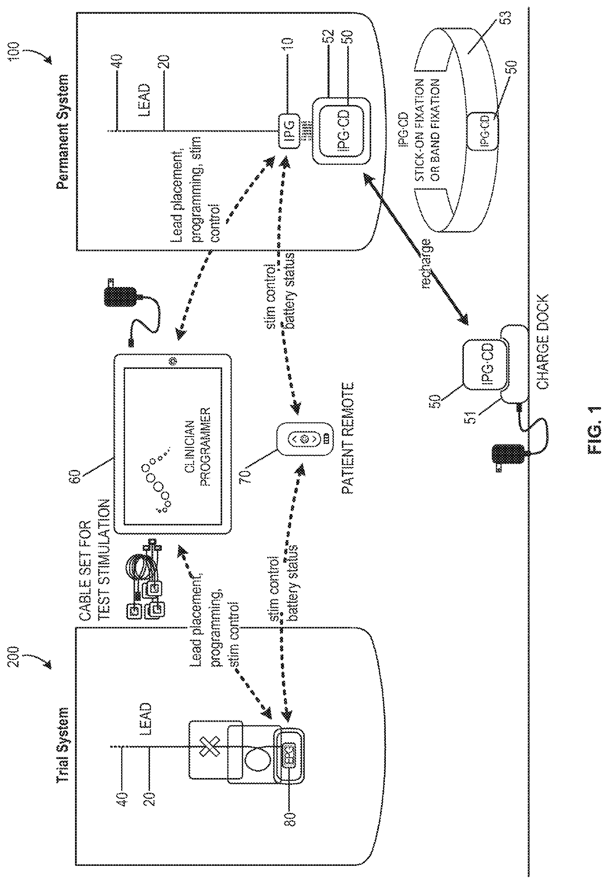
[0051]FIG. 1 schematically illustrates an exemplary nerve stimulation system, which includes both a trial neurostimulation system 200 and a permanently implanted neurostimulation system 100, in accordance with aspects of the invention. The EPG 80 and IPG 10 are each compatible with and wirelessly communicate with a clinician programmer 60 and a patient remote 70, which are used in positioning and / or programming the trial neurostimulation system 200 and / or permanently implanted system 100 after a successful trial. As discussed above, the clinician programmer can include specialized software, specialized hardware, and / or both, to aid in lead placement, programming, re-programming, stimulation control, and / or parameter setting. In addition, each of the IPG and the EPG allows the patient at least some control over stimulation (e.g., initiating a pre-set program, increasing or decreasing stimulation), and / or to monitor battery status with the patient remote. This ap...


PUM


Abstract

Systems and methods for improved power transmission are disclosed herein. The system can include an implantable neurostimulator for delivering the one or more electrical pulses to a patient's body. The implantable neurostimulator can include a hermetic housing made of a biocompatible material, an energy storage feature for powering the implantable neurostimulator, a receiving coil assembly including an elongate wire winding wound around a first ferritic core, and control circuitry for controlling recharging of the energy storage feature. The system can include a charging device for wirelessly delivering energy to the implantable neurostimulator. The charging device can include a sending coil assembly including a planar wire winding coupled to a surface of a second ferritic core.

Description

CROSS-REFERENCES TO RELATED APPLICATIONS[0001]This application claims the benefit of U.S. Provisional Application No. 62 / 816,829, filed Mar. 11, 2019, and entitled “CHARGING DEVICE WITH OFF-CENTER COIL”, the entirety of which is hereby incorporated by reference herein.FIELD[0002]The present invention relates to neurostimulation treatment systems and associated devices, as well as methods of treatment, implantation and configuration of such treatment systems.BACKGROUND[0003]Treatments with implantable neurostimulation systems have become increasingly common in recent years. While such systems have shown promise in treating a number of conditions, effectiveness of treatment may vary considerably between patients. A number of factors may lead to the very different outcomes that patients experience, and viability of treatment can be difficult to determine before implantation. For example, stimulation systems often make use of an array of electrodes to treat one or more target nerve stru...

Claims


Application Information

Patent Timeline
IPC IPC(8): A61N1/378A61N1/05A61N1/36A61N1/372A61N1/02
CPCA61N1/0551A61N1/025A61N1/37223A61N1/3787A61N1/36125
Inventor NASSIF, RABIH
Owner AXONICS
Why Eureka
Try Eureka