Apparatus method for monitoring the I-Q phase bias in an I-Q quadrature modulation transmitter

a quadrature modulation and transmitter technology, applied in pulse technique, phase-modulated carrier systems, instruments, etc., can solve the problems of peak detection method only determining whether, additional optical signal to noise ratio (osnr) penalty, and osnr penalty, so as to improve the accuracy of phase error control

Inactive Publication Date: 2007-10-04
FUJITSU LTD
View PDF1 Cites 29 Cited by
  • Summary
  • Abstract
  • Description
  • Claims
  • Application Information

AI Technical Summary

Benefits of technology

[0020] 3) The precision of the phase error control is improved. The phase error signal output by the phase monitor is proportional to the phase error (i.e. the derivative of the error signal of the phase error is fixed). This feature guarantees that the sensitivity of the phase error signal remains fixed when phase error approaches zero; and
[0021] 4) The speed of the phase control is no longer restricted by the dithering speed, thus quick phase locking can be achieved.

Problems solved by technology

A phase bias different from π / 2 would cause an additional optical signal to noise ratio (OSNR) penalty.
The phase dithering will lead to an additional optical signal to noise ratio (OSNR) penalty.
The peak detection method can only determine whether the phase is at a target value.

Method used


Image

  • Apparatus method for monitoring the I-Q phase bias in an I-Q quadrature modulation transmitter
  • Apparatus method for monitoring the I-Q phase bias in an I-Q quadrature modulation transmitter
  • Apparatus method for monitoring the I-Q phase bias in an I-Q quadrature modulation transmitter

Examples


Embodiment Construction

[0029] Reference will now be made in detail to the embodiments of the present invention, examples of which are illustrated in the accompanying drawings, wherein like reference numerals refer to the like elements throughout. The embodiments are described below to explain the present invention by referring to the figures.

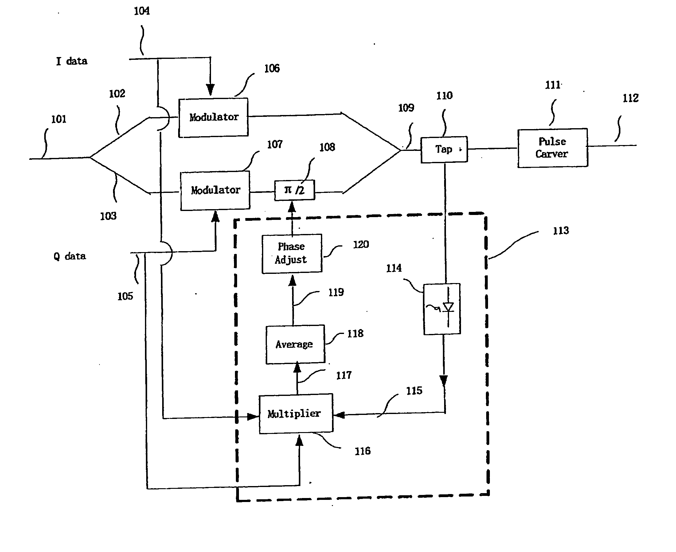
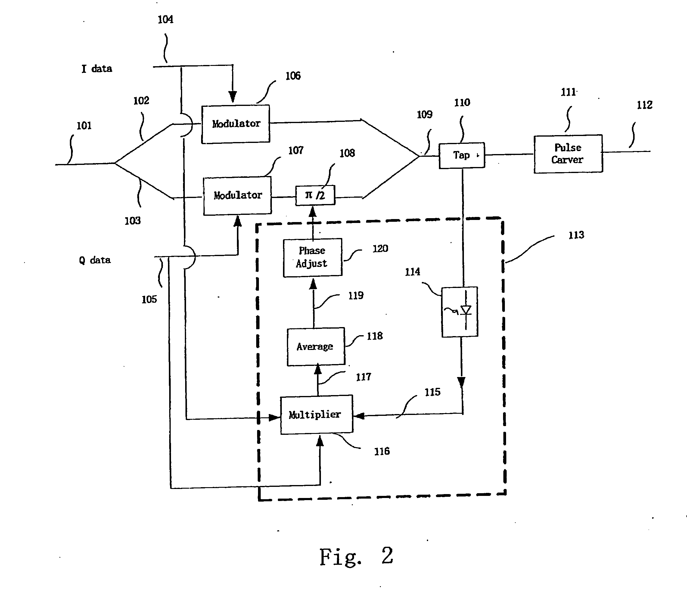
[0030]FIG. 2 is a diagram of a detailed structure of DQPSK transmitter with a I-Q phase bias monitoring apparatus according to an embodiment of the present invention. In FIG. 2, an unmodulated input signal 101 is divided into an I-branch 102 and a Q-branch 103, and each of the I-branch 102 and the Q-branch 103 is equipped with a modulator, 106 and 107, respectively. The modulator 106 and 107 conducts 0 or π phase modulation on the respective signal on the I or the Q branch, which signals carry data 104 and 105, respectively. A phase bias device 108 introduces a phase bias of π / 2 on the Q-branch. The phase bias introduced by the phase bias device 108 must be π / 2, othe...


PUM


Abstract

An apparatus and a method for a I-Q quadrature modulation transmitter monitor a phase bias between an I branch and a Q branch of the I-Q quadrature modulation transmitter. The I-Q quadrature modulation transmitter includes the I-branch, the Q-branch equipped with a phase bias, and a tap. The apparatus is installed between the tap and the phase bias, and monitors the phase between the I branch and the Q branch which phase is introduced by the phase bias. The apparatus includes the following components: a module squarer, receiving signal from the tap and outputting a module square of the received signal; a multiplier, to multiplying data of the I-branch, data of the Q-branch and the module square to output a multiplied signal; and an averager, averaging the multiplied signal output by the multiplier. The phase between the I branch and the Q branch may be corrected according to monitoring results.

Description

CROSS-REFERENCE TO RELATED APPLICATIONS [0001] This application is related to and claims priority from Chinese Application No. 200610065454.2 filed Mar. 22, 2006 in the State Intellectual Property Office of the People's Republic of China, the contents of which are incorporated by reference herein. BACKGROUND OF THE INVENTION [0002] 1. Field of the Invention [0003] The present invention relates to an apparatus and a method for monitoring an I-Q phase bias in an I-Q quadrature modulation transmitter. The method is suitable for a variety of communication systems, optical communication systems or other communication systems, that use in-phase branching and quadrature-phase branching, such as a Differential Quadrature Phase-Shift Key (D QPSK), a Quadrature Phase-Shift Key (QPSK), a Multi Phase-Shift Key (M-PSK), and a Differential Multi Phase-Shift Key (DM-PSK) Quadrature Amplitude Modulation (QAM). [0004] 2. Description of the Related Art [0005] The data transfer capacity of optical com...

Claims


Application Information

Patent Timeline
Patent Type & Authority Applications(United States)
IPC IPC(8): H04L27/12H04L27/20H04L27/36
CPCG02F1/0123H04L27/364H04B10/5561G02F1/2255
Inventor TAO, ZHENNINGRASMUSSEN, JENS C.
Owner FUJITSU LTD
Why Eureka
Try Eureka