
Multiple-input multiple-output spatial multiplexing system with dynamic antenna beam combination selection capability

a spatial multiplexing and multi-input technology, applied in multiplex communication, multi-frequency code systems, polarisation/directional diversity, etc., can solve the problems of reducing performance gain and no criterion for controlling separate rf-aaa, and achieve the effect of maximizing the average signal-to-interference-plus-noise ratio l (sinrs) and minimizing the correlation coefficien

Active Publication Date: 2007-10-04
SONY DEUT GMBH
View PDF22 Cites 70 Cited by
  • Summary
  • Abstract
  • Description
  • Claims
  • Application Information

AI Technical Summary

Benefits of technology

[0008]In view of the above-described prior art, it is the object of the present invention to propose a spatial diversity transmitter and a spatial diversity receiver for a wireless multiple-input multiple-output (MIMO) spatial multiplexing system with an improved BER or PER performance.
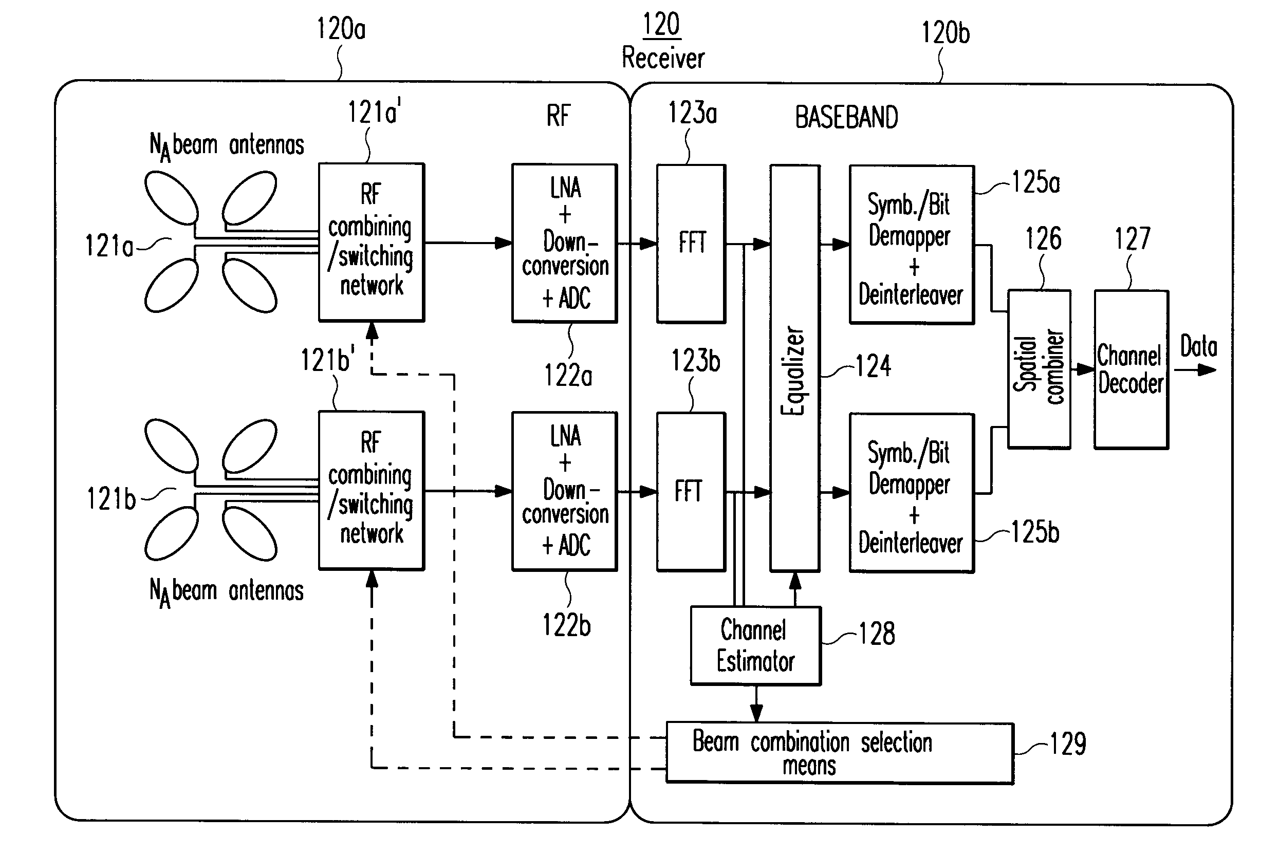
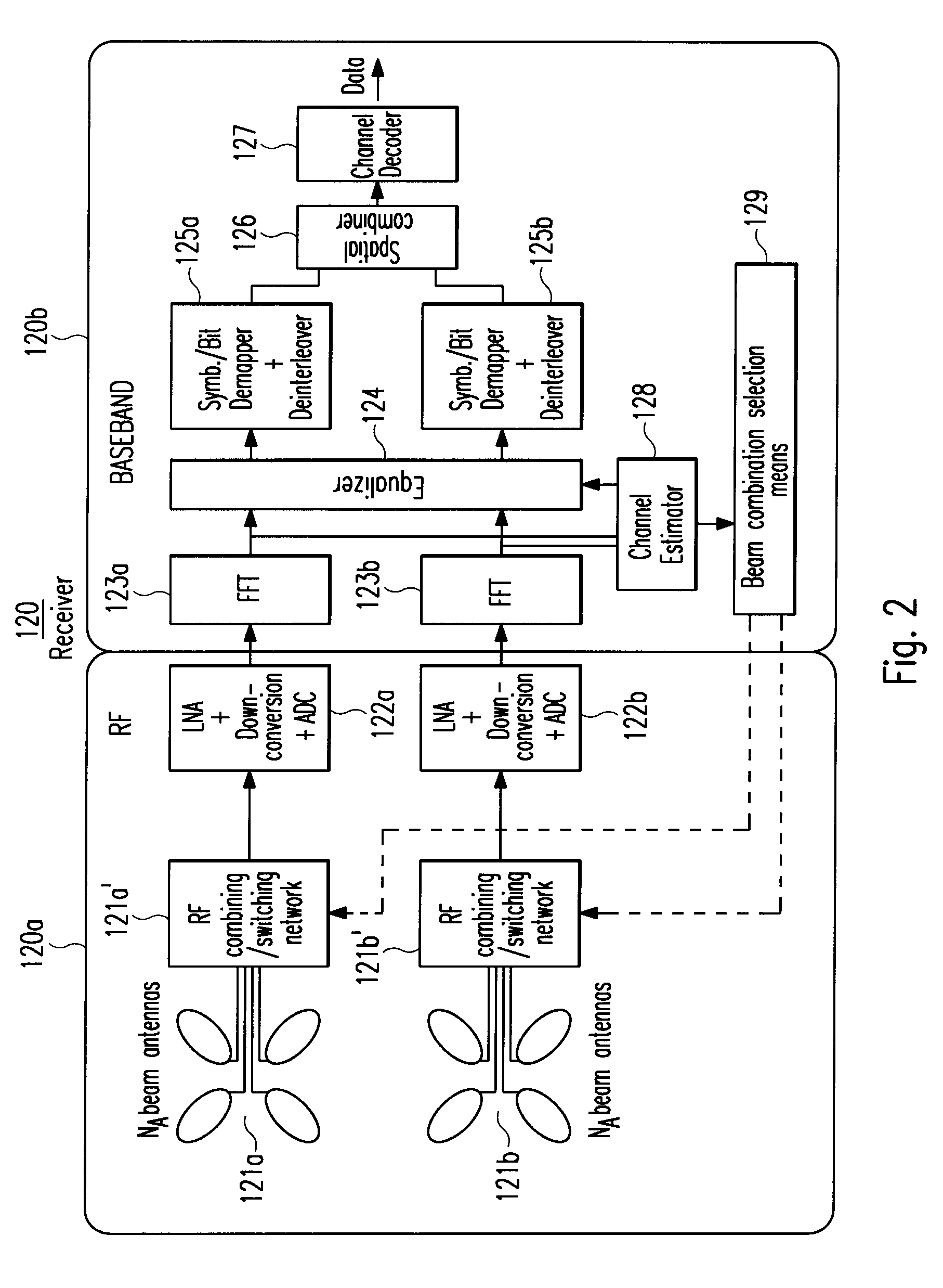
[0012]Said antenna beam selection control means can e.g. be configured for selecting a specific antenna beam combination so as to maximize the average signal-to-interference-plus-noise ratios γl, (SINRs) of RF signals received via said wireless signal propagation paths Pl and / or to minimize the correlation coefficients of different pairs of said RF signals.
[0020]Said antenna beam selection control means can e.g. be configured for selecting a specific antenna beam combination so as to maximize the average signal-to-interference-plus-noise ratios γl (SINRs) of RF signals transmitted via said wireless signal propagation paths Pl and / or to minimize the correlation coefficients of different pairs of these RF signals.
[0025]According to the invention, said method is characterized by the steps of maximizing the average signal-to-interference-plus-noise ratios γl (SINRs) of RF signals received via each signal propagation path Pl and / or minimizing the correlation coefficient indicating the correlation between RF signals received via different signal propagation paths. In a more specific wireless communication scenario, RF signals are only received via a predefined number of the strongest signal propagation paths Pl by the selected combination of fixed beam antennas.

Problems solved by technology

However, performance gain is reduced when the angular spread of the interference is large and when the MIMO radio channel is correlated.
Furthermore, there is no criterion for controlling the separate RF-AAA when the spatial diversity receiver channels are correlated.

Method used


Image

  • Multiple-input multiple-output spatial multiplexing system with dynamic antenna beam combination selection capability
  • Multiple-input multiple-output spatial multiplexing system with dynamic antenna beam combination selection capability
  • Multiple-input multiple-output spatial multiplexing system with dynamic antenna beam combination selection capability

Examples


Embodiment Construction

[0053]In the following, the present invention will be explained in more detail with respect to special embodiments and in relation to the accompanying drawings. The basic principle of the invention will be explained based on a MIMO wireless communication system which uses multi-carrier modulation such as Orthogonal Frequency-Division Multiplexing (OFDM). Of course, the described principle can also be applied to any other not OFDM-based wireless MIMO spatial multiplexing system.

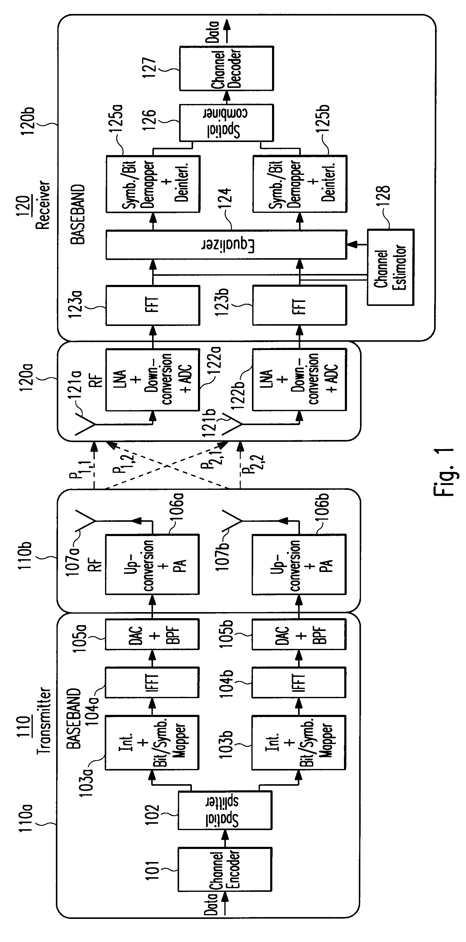
[0054]FIG. 1 shows a block diagram of an OFDM-based wireless MIMO spatial multiplexing system with N=2 transmit antennas 107a and 107b on a wireless transmitter side 110 and M=2 receive antennas 121a and 121b on a wireless receiver side 120, wherein the transmit antennas 107a+b and / or the receive antennas 121a+b may e.g. be realized as fixed beam antennas. The achievable data transmission rate R is therefore two times higher than in a non-MIMO wireless communication system. In this connection, it

should be ment...


PUM


Abstract

The present invention generally relates to the field of wireless communication systems. It particularly refers to a spatial diversity transmitter (110) and a spatial diversity receiver (120) in a wireless multiple-input multiple-output (MIMO) spatial multiplexing system as well as a corresponding method for wirelessly transmitting and receiving modulated RF signals via multiple wireless signal propagation paths (Pl) of a multipath fading channel in a way that correlation between the MEMO channel components are reduced and / or the signal to interference plus noise ratio (SINR) is increased which hence result in an improved bit error rate (BER) or packet error rate (PER) performance of said wireless MIMO spatial multiplexing system. On the receiver side, for example, this is achieved by controlling at least one antenna switching and / or combining means (121a′+b′) to select a specific combination of different fixed beam antennas (121a+b) from each receiver-resident antenna array. According to the invention, said selection is based on estimated values of the channel impulse responses (hl(τl, t)) for said signal propagation paths (Pl). An antenna beam selection control means (129) is configured for selecting a specific antenna beam combination so as to maximize the average signal-to-interference-plus-noise ratios ( γl) of RF signals (rl(τl, t, φl)) received via said multiple wireless signal propagation paths (Pl) and / or to minimize the correlation coefficients (ρr<sub2>l1< / sub2>r<sub2>l2< / sub2>(t)) indicating the correlations of different pairs of these RF signals (rl1(τl1, t, φl1) and rl2(τl2, t, φl2)).Thereby, each fixed beam antenna (121a+b) of the receiver-resident antenna arrays has a distinct radiation pattern with a different beam center and / or beam width in the azimuth and / or elevation plane, wherein a superposition of all these radiation patterns may cover all possible azimuthal (φ) and / or elevational angles of arrival (θ) of an RF signal (s(t)).For compensating detected multipath fades in the channel amplitude response (|Hl(f, t)|) of at least one signal propagation path (Pl) between the spatial diversity transmitter (110) and the spatial diversity receiver (120), a receiver-resident channel estimation and / or equalization circuitry (124, 128) is applied.

Description

FIELD AND BACKGROUND OF THE INVENTION[0001]The present invention generally relates to the field of wireless communication systems. It particularly refers to a spatial diversity transmitter ad a spatial diversity receiver in a wireless communication system, as well as a corresponding method for wirelessly transmitting ad receiving modulated RF signals. The present invention is specifically advantageous but not exclusively limited to the application in a multiple-input multiple-output (MIMO) spatial multiplexing system and enables reception and transmission of said RF signals via multiple wireless signal propagation paths of a multipath fading channel in a way that correlation between the MIMO channel components are reduced and / or the signal to interference plus noise ratio (SINR) is increased. This results in an improved bit error rate (BER) or packet error rate (PER) performance of said wireless MIMO spatial multiplexing system.[0002]Spatial diversity techniques have been shown to p...

Claims


Application Information

Patent Timeline
Patent Type & Authority Applications(United States)
IPC IPC(8): H04L1/02H04J99/00
CPCH04B7/0408H04B7/0691H04B7/0695H04L27/00H04B7/0874H04B7/088H04B7/0857
Inventor STIRLING-GALLACHER, RICHARD
Owner SONY DEUT GMBH
Learn More