Optical power monitor

a technology power monitors, applied in the field of optical power monitors, can solve the problems of requiring the reduction of the size of each power monitor, the difficulty of reducing the size of the product, and the difficulty so as to achieve the effect of reducing the responsivity variation range, high responsivity, and reducing the size of the power monitor

Inactive Publication Date: 2007-10-04
HITACHI METALS LTD
View PDF7 Cites 13 Cited by
  • Summary
  • Abstract
  • Description
  • Claims
  • Application Information

AI Technical Summary

Benefits of technology

[0048]Preferably, in the optical power monitor of the present invention, the distance between the first and the second support blocks is 4.8 mm to 14.0 mm, and each of the distance between the first support block and the fusion splicing portion and the distance between the light reflection surface and the second support block is 0.2 mm to 2.0 mm. By selecting this size, an optical power monitor small in size and having a high responsivity and a reduced responsivity variation range can be obtained.
[0049]The optical power monitor of the present invention has two optical fibers provided on the light transmission upstream and downstream sides and having cores, the end surfaces which are opposed to each other with the core optical axes offset from each other, and which are fusion-spliced to each other in a fusion splicing portion, a light reflection surface which faces a portion of the upstream-side optical fiber core end surface offset to protrude from the downstream-side optical fiber core end surface in the fusion splicing portion, and which is provided in the downstream-side optical fiber cladding layer, and a photo-diode positioned opposite from the light reflection surface with respect to the downstream-side optical fiber core. Third-order or fourth-order lights strengthening each other in lights leaked into the downstream-side optical fiber cladding layer from the upstream-side optical fiber core end surface are reflected by the reflection surface provided in the cladding layer and detected with the photo-diode. Thus, the present invention has made it possible to provide an optical power monitor capable of being reduced in size even when designed as a multi-channel monitor, and having a reduced light transmission loss.
[0050]The optical power monitor of the present invention may further have a first support block holding the upstream-side optical fiber on the upstream side of the fusion splicing portion and a second support block holding the downstream-side optical fiber on the downstream side of the light reflection surface. The part of the two optical fibers between the first and second support blocks is curved in an arc-like shape to rise in a direction opposite to the direction toward the photo-diode. In this case, the responsivity can be further improved and the responsivity variation range can be reduced.

Problems solved by technology

This method requires fusion splicing connection of each component, which is a hindrance to the reduction in the number of mounting steps.
It is, therefore, difficult to reduce the size of the product.
Since the housing space in a unit assignable to optical power monitors is limited, a reduction in size of each power monitor is necessarily required.
It is, therefore, difficult to reduce the overall size of the optical power monitor assembly 71 shown in FIG. 17A.
It is also well known that the light loss in the portions connecting the waveguides and the optical fibers is large.
It is difficult to reduce the loss.
Since the light emitted into the air is separated by the reflecting filter into light traveling to the output side and light entering the photo-detector, it is difficult to reduce the light loss.
The product size is further increased thereby and it is difficult to reduce the overall size.

Method used


Image

  • Optical power monitor
  • Optical power monitor
  • Optical power monitor

Examples


example 1

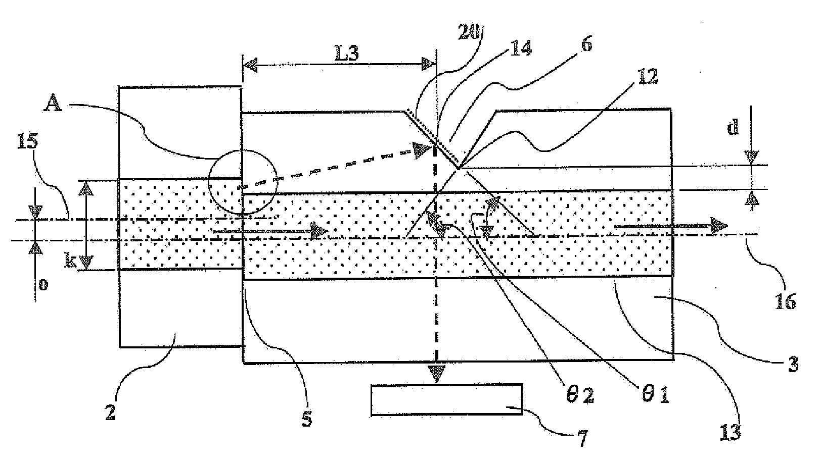
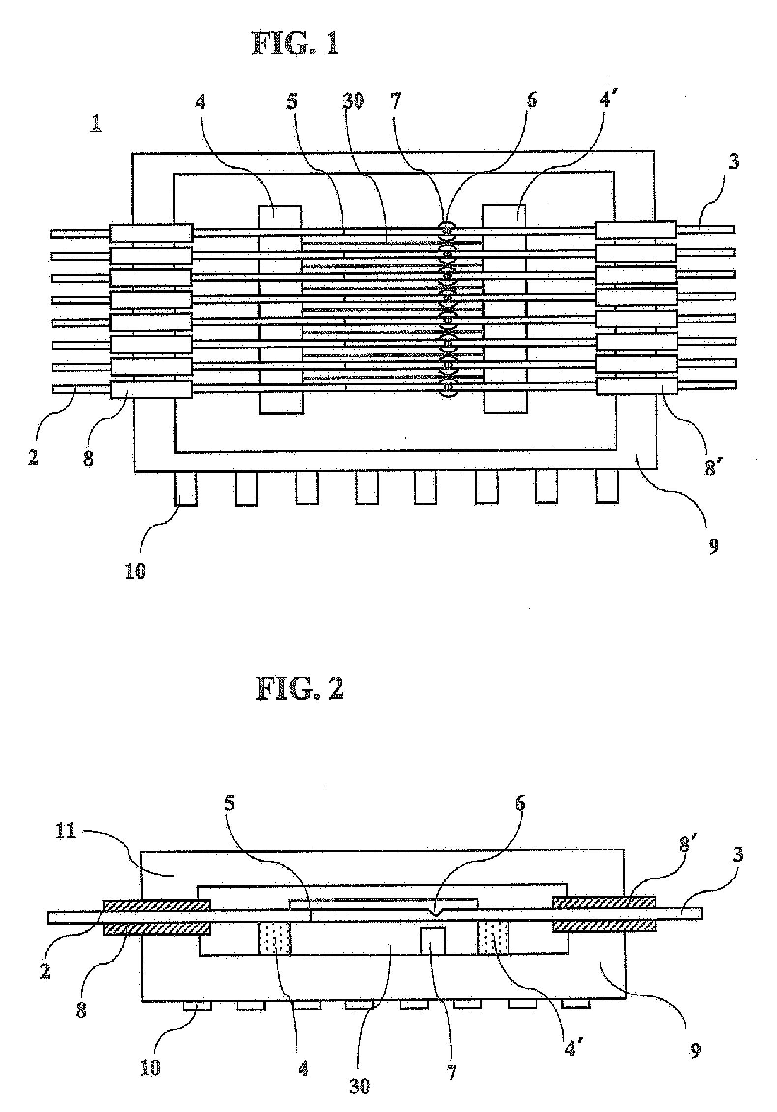
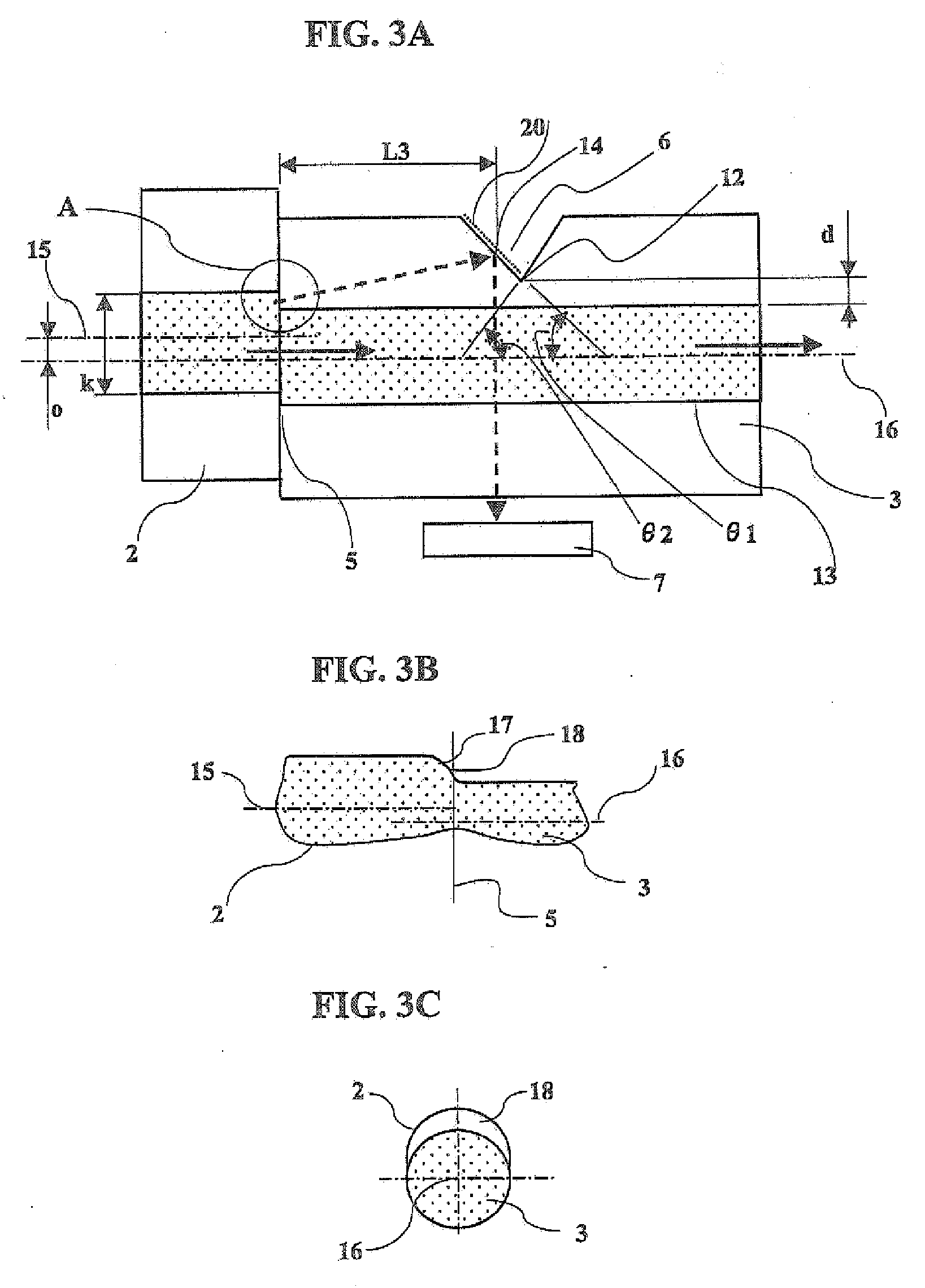
[0070]FIG. 1 is a plan view of an optical power monitor of the present invention in a state where an upper lid is removed. FIG. 2 is a longitudinal sectional view of the optical power monitor. FIG. 3A is an enlarged longitudinal sectional view for explaining a fusion splicing portion between two optical fibers and a notch in the downstream-side optical fiber. FIG. 3B is an enlarged longitudinal sectional view along an offset plane for explaining the fusion splicing portion between the two optical fibers. FIG. 3C is a transverse sectional view for explaining the fusion splicing portion. FIGS. 4A and 4B are schematic diagrams for explaining travel of light leaked into a cladding layer from a core of the fusion splicing portion.

[0071]The structure of an optical power monitor assembly 1 of the present invention will be described in detail with reference to FIGS. 1 and 2. FIG. 1 shows an 8-channel optical power monitor assembly 1 having eight optical power monitors housed in a case 9. Li...

example 2

[0077]FIG. 5 is a graph showing the relationship between the responsivity (mA / W) of the photodiode and the distance L3 (mm) between the fusion splicing portion and the light reflection surface. The responsivity was measured while changing the distance L3 between the fusion splicing portion and the light reflection surface from 0.8 mm to 9.0 mm. The factors other than the distance L3, i.e., the shape (angle), the size of the notch, the light reflecting metal film and so on, were the same as those in EXAMPLE 1. It can be understood that the responsivity was high when the distance L3 between the fusion splicing portion and the light reflection surface was about 1 mm, when the distance was about 3 mm, when the distance was about 5 mm, when the distance was about 7 mm and when the distance was about 9 mm, and that the responsivity was low when the distance was about 2 mm, when the distance was about 4 mm, when the distance was about 6 mm and when the distance was about 8 mm. High-respons...

example 3

[0078]FIG. 6 is a graph showing the relationship between the responsivity (mA / W) and the angle θ1 (°) of the light reflection surface to the downstream-side core optical axis. 4i The distance L between the fusion splicing portion and the light reflection surface was fixed at 6.80 mm and fourth-order interference light was used. Optical power monitors were made by changing the angle θ1 of the light reflection surface from 28° to 60°. The responsivity measuring method, the light reflecting film and so on in EXAMPLE 3 are the same as those in EXAMPLE 1. The responsivity was higher than 60 mA / W when the angle θ1 was in the range from 38° to 45°, but decreased abruptly when the angle was reduced below 38° and when the angle exceeded 45°. The following is thought to be the cause of the reduction in responsivity. When the angle is smaller than 38°, light is reflected by the light reflection surface but angle at which the reflected light is radiated to the optical fiber periphery is increas...


PUM


Abstract

An optical power monitor capable of being reduced in size even when designed as a multi-channel monitor, and having a reduced light transmission loss is disclosed. The optical power monitor has two optical fibers provided on the light transmission upstream and downstream sides and having cores, the end surfaces which are opposed to each other with the core optical axes offset from each other, and which are fusion-spliced to each other in a fusion splicing portion, a light reflection surface which faces a portion of the upstream-side optical fiber core end surface offset to protrude from the downstream-side optical fiber core end surface in the fusion splicing portion, and which is provided in the downstream-side optical fiber cladding layer, and a photo-diode positioned opposite from the light reflection surface with respect to the downstream-side optical fiber core. Third-order or fourth-order lights strengthening each other in lights leaked into the downstream-side optical fiber cladding layer from the upstream-side optical fiber core end surface are reflected by the reflection surface provided in the cladding layer and detected with the photo-diode.

Description

BACKGROUND OF THE INVENTION[0001]1. Field of the Invention[0002]The present invention relates to an optical power monitor used mainly in the field of optical communication.[0003]2. Description of the Related Art[0004]In recent years, remarkable technological innovation on information communication has been brought about, and a transition from communication by an electrical signal to communication by an optical signal is being made to meet the demand for increasing the communication speed and to cope with the increase in the amount of information with the proliferation of the internet. On many of trunk cables, information from a multiplicity of relay points concentrates. Therefore, the conventional trunk cables are being replaced with optical cables advantageous in terms of processing capacity and rate. Restudy of communication between optical cables and user terminals has been started and there is an increasing demand for implementing a more comfortable information environment at a ...

Claims


Application Information

Patent Timeline
Patent Type & Authority Applications(United States)
IPC IPC(8): G02B6/26
CPCG02B6/4249G02B6/4214G02B6/43G02B6/255
Inventor SUZUKI, MASARUAO, MASAHIROFUKUYAMA, TAKESHI
Owner HITACHI METALS LTD
Why Eureka
Try Eureka