Rotary Blood Pump

a rotary, blood pump technology, applied in the direction of machines/engines, mechanical equipment, liquid fuel engines, etc., can solve the problems of hemolysis or thrombosis, design a more perfect blood pump, passing through the pump, etc., to achieve efficient pumping of blood through the circulatory system of patients, reduce power consumption, and minimize damage to patients' blood.

Inactive Publication Date: 2007-10-04
TC1 LLC
View PDF99 Cites 78 Cited by
  • Summary
  • Abstract
  • Description
  • Claims
  • Application Information

AI Technical Summary

Benefits of technology

[0010] It is another object of the present invention to provide a rotary pump that minimizes damage to a patient's blood.
[0011] It is yet another object of the present invention to provide a rotary pump that in

Problems solved by technology

However, the fragile nature of blood and the absolute necessity of the pump's reliability have presented numerous obstacles to designing a more perfect blood pump.
If these moving parts are not properly designed and adjusted, the blood passing through the pump can be damaged, causing hemolysis or thrombosis.
Further, these moving parts can wear on each other, causing an increased likelihood of part failure and heat buildup that is imparted to the blood.
Both blood pumps suffer from hydraulic inefficiencies du

Method used


Image

  • Rotary Blood Pump
  • Rotary Blood Pump
  • Rotary Blood Pump

Examples


Embodiment Construction

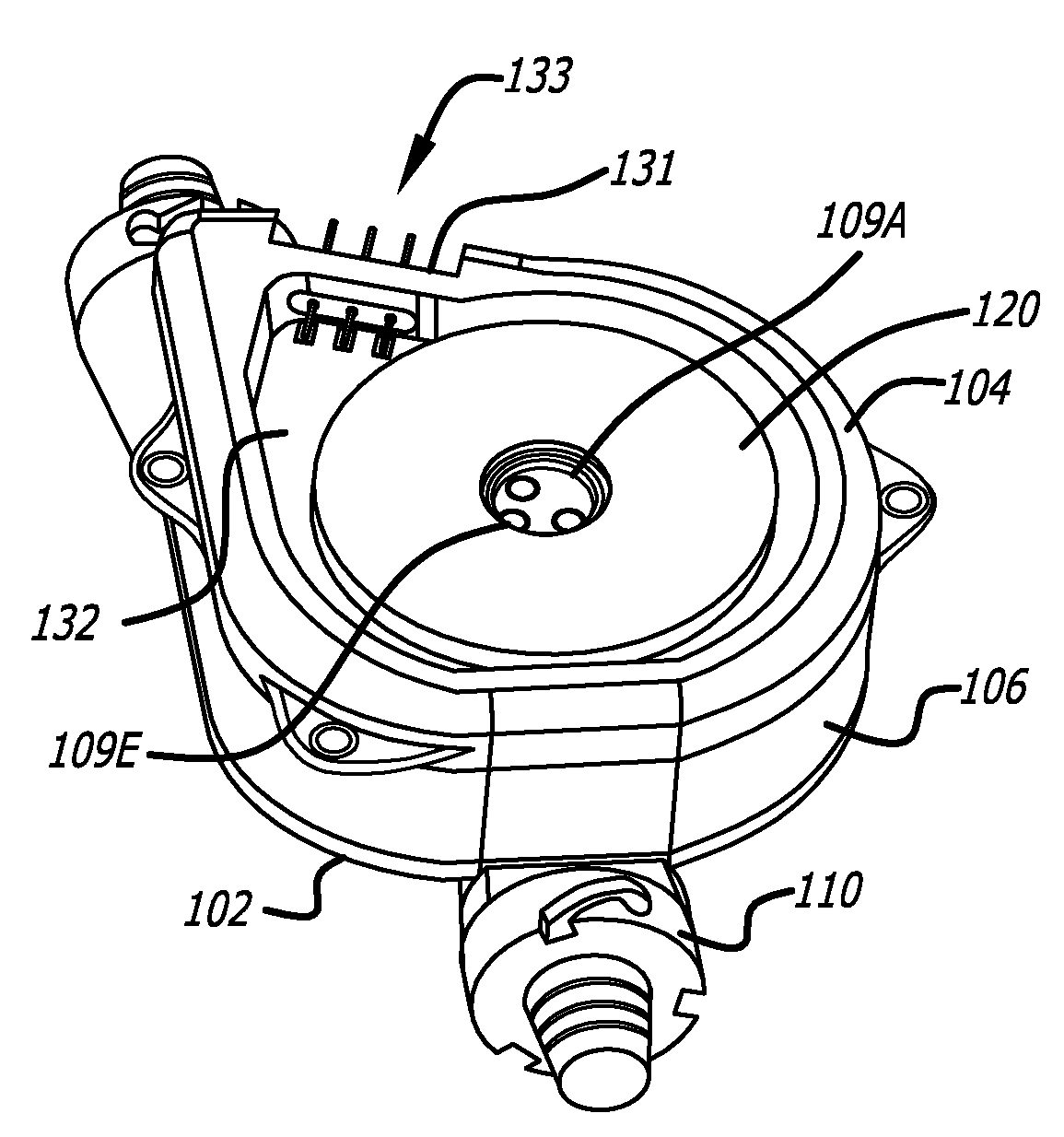
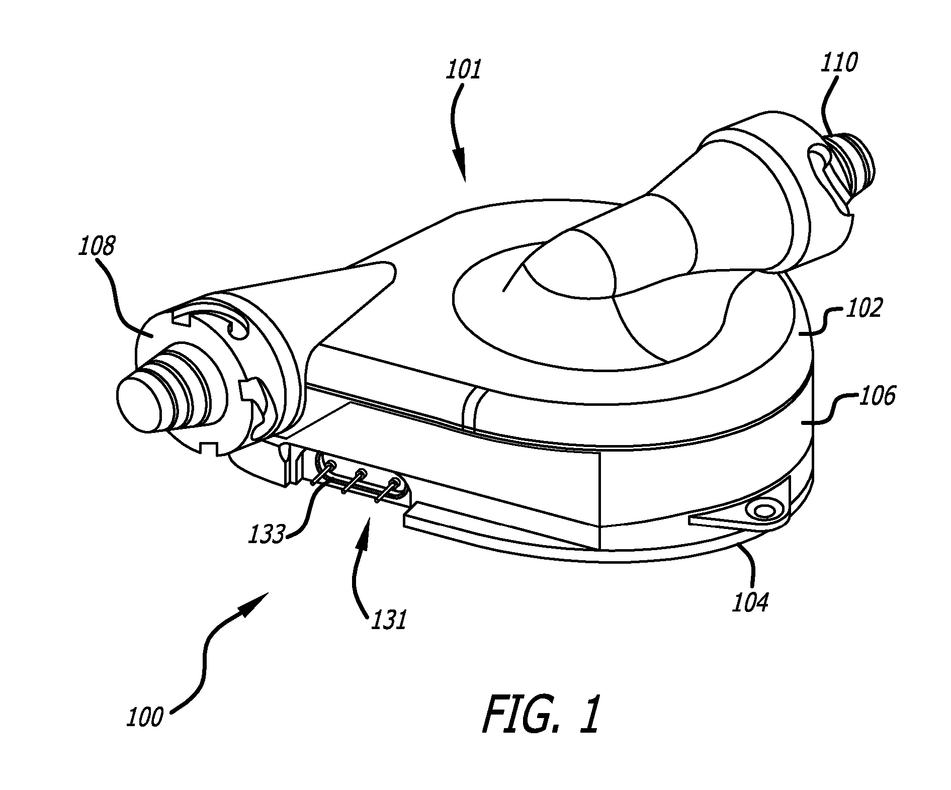
[0109]FIG. 1 illustrates a preferred embodiment of a rotary blood pump 100 according to the present invention. The rotary blood pump 100 is coupled to the circulatory system of a patient, allowing blood to enter through an inlet 110 then exit a short time later through an outlet 108.

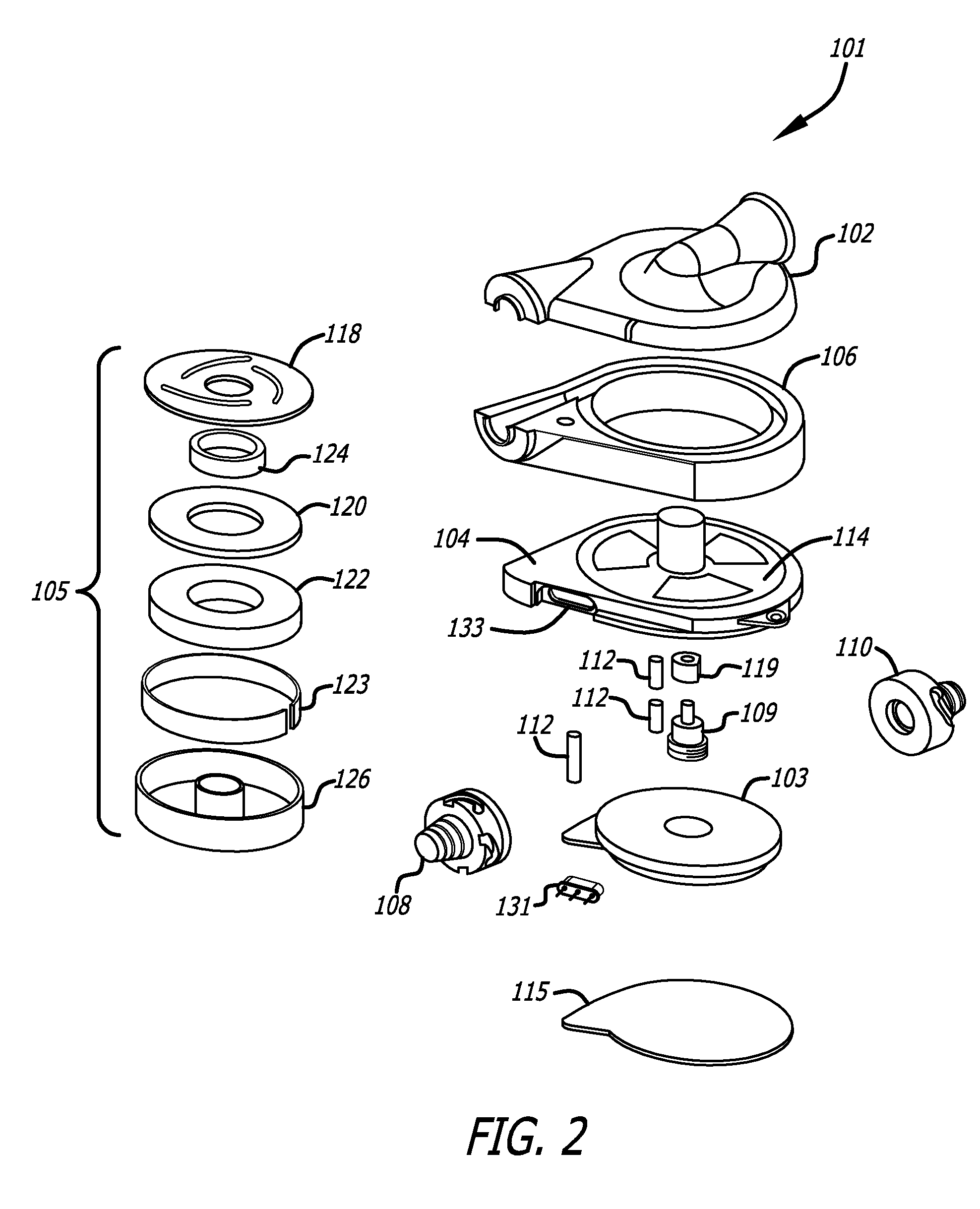
[0110] Blood is primarily driven through the rotary blood pump 100 by a rotor assembly 105 within a housing assembly 101, as seen in FIG. 2. The rotor assembly 105 is not physically connected to the housing assembly 101. Instead, the rotor assembly 105 is supported by an axial hydrodynamic bearing created between a thrust plate 114 and a bottom surface of the rotor assembly 105, a radial hydrodynamic bearing between the inside diameter of the rotor assembly 105 and the outside diameter of the spindle portion of the thrust plate 114 (or, in the alternative, between the outside of the rotor assembly 105 and the inside diameter of the housing assembly 101), and by an axial magnetic bearing created between ...


PUM


Abstract

The present invention provides a rotary blood pump with both an attractive magnetic axial bearing and a hydrodynamic bearing. In one embodiment according to the present invention, a rotary pump includes an impeller assembly supported within a pump housing assembly by a magnetic axial bearing and a hydrodynamic bearing. The magnetic axial bearing includes at least two magnets oriented to attract each other. One magnet is positioned in the spindle of the pump housing while the other is disposed within the rotor assembly, proximate to the spindle. In this respect, the two magnets create an attractive axial force that at least partially maintains the relative axial position of the rotor assembly. The hydrodynamic bearing is formed between sloping surfaces that form tight clearances below the rotor assembly.

Description

RELATED APPLICATIONS [0001] This application claims priority to U.S. Provisional Application Ser. No. 60 / 787,738 filed Mar. 31, 2006 entitled Rotary Blood Pump which is hereby incorporated by reference.BACKGROUND OF THE INVENTION [0002] Blood pumps remain particularly useful for the treatment of cardiac disease and especially heart failure. Typically, blood pumps are implanted within a patient and connected to the patient's circulatory system as a ventricular assist device or, in some circumstances, as an artificial heart. However, the fragile nature of blood and the absolute necessity of the pump's reliability have presented numerous obstacles to designing a more perfect blood pump. [0003] For example, most blood pumps contain moving parts, such as an impeller, that force blood into and out of the pump housing. If these moving parts are not properly designed and adjusted, the blood passing through the pump can be damaged, causing hemolysis or thrombosis. Further, these moving parts...

Claims


Application Information

Patent Timeline
IPC IPC(8): F04D29/04A61M60/178A61M60/232A61M60/422A61M60/81A61M60/82
CPCA61M1/101F04D29/0413A61M1/1017F04D29/0476A61M1/1015F04D29/048A61M60/824A61M60/422A61M60/148A61M60/81A61M60/232A61M60/178A61M60/419F04D29/0473F04D29/2266F04D29/426A61F2/24A61M60/205A61M60/82
Inventor WAMPLER, RICHARD K.LANCISI, DAVID M.
Owner TC1 LLC
Why Eureka
Try Eureka