
Method and apparatus for applying continuous flow and uniform temperature to generate thermal melting curves in a microfluidic device

a microfluidic device and thermal melting curve technology, applied in fluid controllers, biochemistry apparatus and processes, laboratory glassware, etc., can solve problems such as loss of fluorescent signal due to dye photobleaching and inability to integrate well in systems

Inactive Publication Date: 2007-10-04
CANON US LIFE SCIENCES INC
View PDF17 Cites 47 Cited by
  • Summary
  • Abstract
  • Description
  • Claims
  • Application Information

AI Technical Summary

Benefits of technology

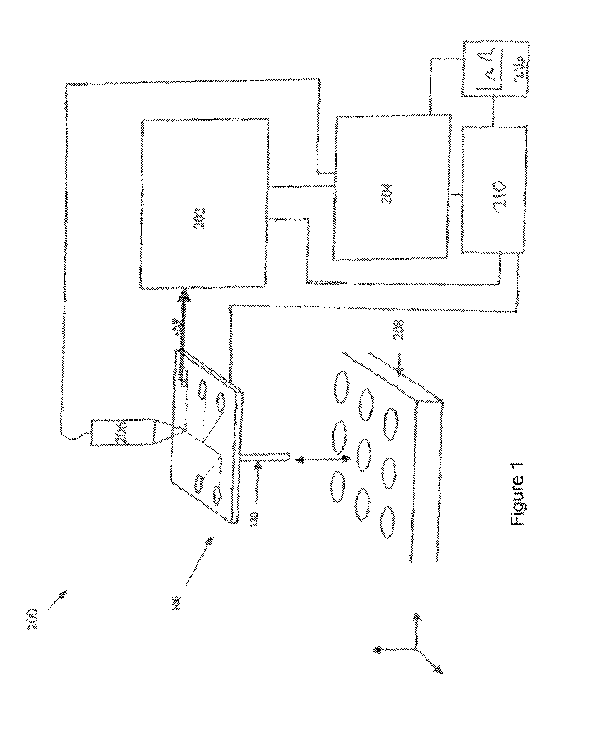
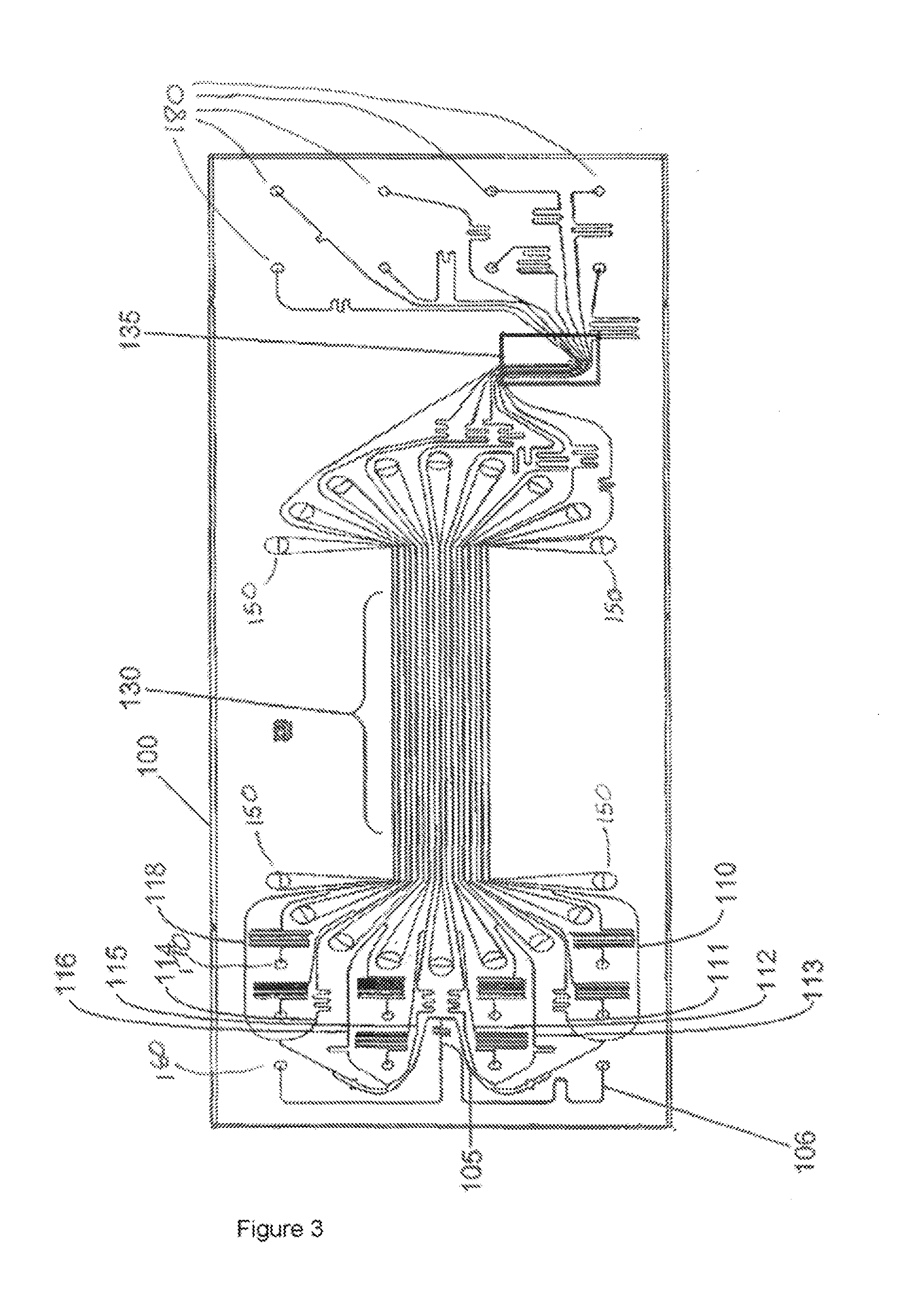
[0026]Joule heating in the integrated system or microfluidic device of the invention comprises the flow of a selectable electric current through the at least one microchannel, thereby elevating the temperature. Joule heating can be applied uniformly over the entire length of the microchannel, maintaining a consistent cross-sectional area of the channel. The level of joule heating is controlled by changing the selectable current, the electrical resistance of the fluid in the channel, or both the current and the resistance. The selectable current may comprise a direct current, an alternating current or a combination of direct current and alternating current.
[0027]Optionally, the integrated system or microfluidic device of the invention includes non-joule heating through an internal or external heat source. In some embodiments, the internal or external heat source may comprise one or more of a thermal heating block. Peltier device, resistive heating element, thermoelectric gas or liquid that transfers heat conductively or convectively. Just as for joule heating, non-joule heating optionally can produce a uniform temperature over the entire length of the microchannel.
[0028]In another embodiment of the invention, the integrated system or microfluidic device optionally provides at least one fluorescence indicator dye or fluorescence indicator molecule capable of binding to one or more hydrophobic amino acid residues, one ore more hydrophillic amino acid residues, or a combination thereof, of another molecule. For example, the fluorescence indicator dye or fluorescence indicator molecule comprises, e.g., 1-analino-naphthalene-8-sulfonate. In another embodiment, the fluorescence indicator dye or fluorescence indicator molecule can intercalate into, or bind by another mechanism to, one or more nucleic acid polymers.
[0029]In various embodiments, an integrated system or microfluidic device in accordance with the invention may comprise a high-through-put format, a low-throughput throughput format, or a multiplex format. In many embodiments of the invention the excitation source for exciting the fluorescence indicator dye or fluorescence indicator molecule comprises a light source. For example, the light source may comprise one of more of a tungsten-halogen lamp, a xenon-arc lamp, a mercury lamp, a laser, an LED, or a fiber optic cable. Some embodiments of the integrated system comprise an array of light sources to excite fluorescence at a plurality of locations along the length of a microchannel in the microfluidic device.
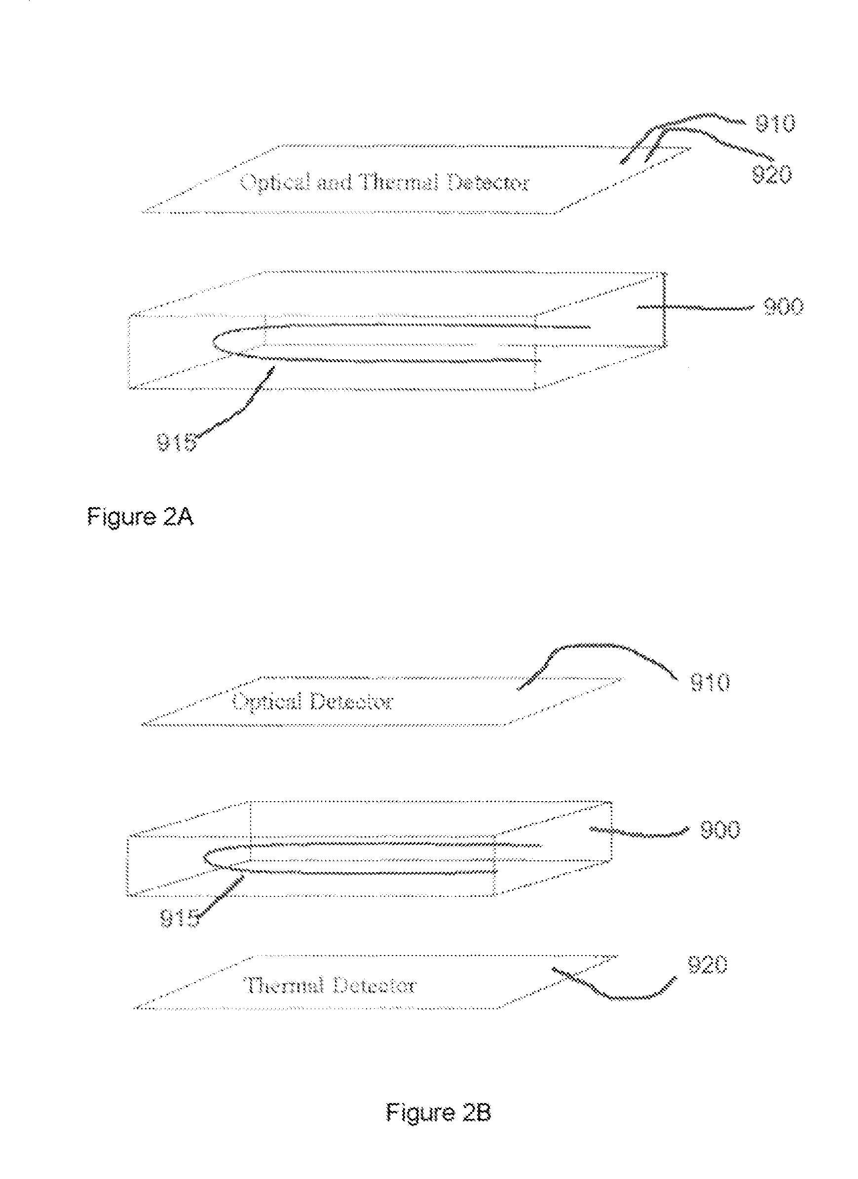
[0030]An integrated system in accordance with the invention may comprise one or more of the following types of optical dectectors: a fiber optic probe, a charge coupled device, a fluorescence imaging camera, a photomultiplier, a photodiode, or a more of the following types of optical detectors: a fiber optic probe, a charge coupled device, a fluorescence imaging camera, a photomultiplier, a photodiode, or a fluorescence polarization sensor. The system may also comprise an array of optical detectors to measure optical signals emanating from a plurality of locations along the length of a microchannel in the microfluidic device. Additionally, an integrated system in accordance with the invention may comprise one or more of the following types of temperature detectors: contact temperature detectors such as thermocouples, resistance temperature detectors, or thermistors; or non-contact temperature detectors such as IR thermometers or optical pyrometers. The system may also comprise an array of temperature detectors to measure the temperature at a plurality of locations along the length of a microchannel in the microfluidic device. The optical detector optionally has the ability to detect fluorescence or emitted from an excited fluorescence indicator dye or molecule or optionally has the ability to detect a change in the thermal parameters of the system comprising the molecule(s) in the at least one microchannel.

Problems solved by technology

A drawback to stopped flow format is that is does not integrated well in systems with other flow through processes which require the flow to continue without any stoppage.
When fluorescent indicator dyes are used to monitor denaturation, another drawback to stopped flow format is the loss of fluorescent signal due to dye photobleaching while the thermal ramp is being performed.
A drawback to current implementations of continuous flow microchannel controlled to the first temperature, and the temperature at the other end of the length is controlled to the second temperature thus creating a continuous temperature gradient spanning the temperature range between the first and second selected temperatures.
A drawback to current implementations of continuous flow format is that thermal properties of the molecules in the stream must be measured at multiple points along the temperature gradient to generate the desired melting curve.

Method used


Image

  • Method and apparatus for applying continuous flow and uniform temperature to generate thermal melting curves in a microfluidic device
  • Method and apparatus for applying continuous flow and uniform temperature to generate thermal melting curves in a microfluidic device
  • Method and apparatus for applying continuous flow and uniform temperature to generate thermal melting curves in a microfluidic device

Examples


Embodiment Construction

[0036]Methods and devices in accordance with the invention are capable of rapidly characterizing a variety of biological materials via the generation of molecular melt curves. For example, the molecular melt curve of a double stranded DNA molecule can provide information about the number of base pairs in the molecule, the GC content, and the amount of variation from ideal Watson-Crick base pairing. A molecular melt curve also can be used to indicate the degree of binding between one or more test molecules and a target molecule. “Binding” includes not only, e.g., receptor-ligand interactions, but also, e.g,., nucleic acid-nucleic acid hybridization interactions and can include both specific and nonspecific interaction. If the test molecules do bind to the target molecule, then their binding can be quantified by the invention. The methods and devices herein are flexible and can be applied to many different types of compounds and molecules. For example, both the target molecule and the...


PUM

PropertyMeasurementUnit
timeaaaaaaaaaa
timeaaaaaaaaaa
angleaaaaaaaaaa

Abstract

The present invention provides a method for performing thermal melt analysis using a microfluidic device, the method comprising providing a microfluidic device having at least one microfluidic channel, introducing fluid comprising into the at least one microfluidic channel, continuously flowing the fluid through the at least one microfluidic channel while varying the temperature of the entire fluid stream as it moves through the at least one microfluidic channel by uniformly heating the entire fluid stream, and measuring, while continuously flowing the fluid through the at least one microfluidic channel, a detectable property emanating from the fluid,

Description

CROSS-REFERENCE TO RELATED APPLICATION[0001]This application claims the benefit of U.S. Provisional Application No. 60 / 786,565, filed Mar. 28, 2006, which is hereby incorporated by reference in its entirety.FIELD OF INVENTION [0002]The present invention relates to the characterization of biological materials on a microfluidic device. More particularly, the present invention is directed towards determining the thermal properties of biological materials on a microfluidic device.BACKGROUND OF THE INVENTION [0003]When carrying out chemical or biochemical analyses, assays, syntheses or preparations, a large number of separate manipulations are performed on the material or component to be assayed, including measuring, aliquotting, transferring, diluting, mixing, separating, detecting, incubating, etc. Microfluidic technology miniaturizes these manipulations and integrates them so that they can be executed within one or a few microfluidic devices.[0004]For example, pioneering microfluidic ...

Claims


Application Information

Patent Timeline
Patent Type & Authority Applications(United States)
IPC IPC(8): C12Q1/68
CPCB01L3/502715B01L7/525B01L2300/1805B01L2300/1827B01L2400/06B01L2400/0415B01L2400/043B01L2400/0487B01L2300/1833C12Q1/6813
Inventor KNIGHT, IVOR T.BOYLES, DEBORAH J.
Owner CANON US LIFE SCIENCES INC
Learn More