Check patentability & draft patents in minutes with Patsnap Eureka AI!

Bus width automatic adjusting method and system

a technology of automatic adjustment and bus width, applied in the field of computer hardware technology, to achieve the effect of optimizing the data transmission ra

Inactive Publication Date: 2007-10-04
INVENTEC CORP
View PDF13 Cites 9 Cited by
  • Summary
  • Abstract
  • Description
  • Claims
  • Application Information

AI Technical Summary

Benefits of technology

[0007] It is therefore an objective of this invention to provide a bus width automatic adjusting method and system which can provide a PCIe interface controller with a bus width automatic adjusting function that allows the PCIe interface controller to automatically adjust the width of the bus in response to different card plugging conditions of the connecting slots on the motherboard so as to allow the PCIe interface controller to always have optimal performance in data communication with the plugged circuit card(s).
[0011] The bus width automatic adjusting method and system according to the invention is characterized by dividing the bus of the interface controller on the computer platform and the bus of each connecting slot into two half-width portions such that the two half-width portions of the bus of the interface controller can be selectively connected to either just one slot or two slots depending on the current card plugging status of the slots on the motherboard of the computer platform. This feature allows the user to plug just one circuit card to one connecting slot on the motherboard or two circuit cards respectively to two connecting slots on the motherboard, and notwithstanding allow the plugged circuit board(s) to function normally and operate at the optimal data transmission rate.

Problems solved by technology

In practical implementation, however, one problem to the above-mentioned PCIe bus architecture is that if a PCIe interface controller has an 8-bit bus, then in circuit design, the 8-bit bus can only be used in the following 2 ways: first, connecting all the 8-bit bus lines to one single slot; and second, dividing the 8-bit bus into two 4-bit portions for use to be connected to two slots respectively.

Method used


Image

  • Bus width automatic adjusting method and system
  • Bus width automatic adjusting method and system
  • Bus width automatic adjusting method and system

Examples


Embodiment Construction

[0017] The bus width automatic adjusting method and system according to the invention is disclosed in full details by way of preferred embodiments in the following with reference to the accompanying drawings.

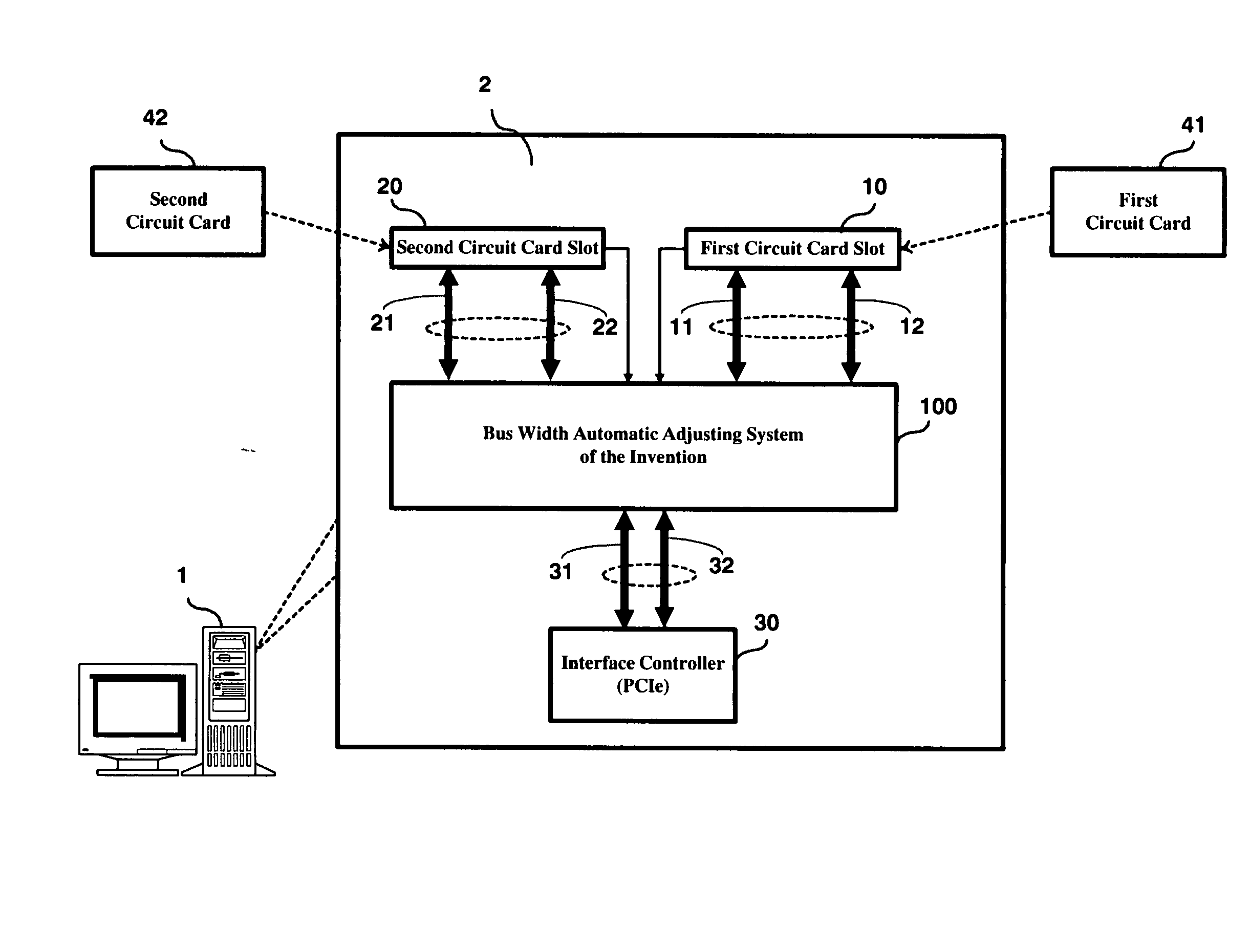
[0018]FIG. 1 is a schematic diagram showing the application of the bus width automatic adjusting system according to the invention (as the block indicated by the reference numeral 100). As shown, the bus width automatic adjusting system of the invention 100 is designed for use in conjunction with a computer platform 1, such as a desktop computer or a network server, for integration to the motherboard 2 of the computer platform 1 that is equipped with a special type of bus architecture having at least one interface controller 30 and at least two circuit card slots, including a first circuit card slot 10 and a second circuit card slot 20. In accordance with the invention, the first circuit card slot 10 is connected to a bus that is divided into a first half-portion bus 11 and a s...


PUM


Abstract

A bus width automatic adjusting method and system is proposed, which is designed for use with a computer platform for providing the computer platform with a bus width automatic adjusting function; and which is characterized by dividing the bus of the interface controller on the computer platform and the bus of each connecting slot into two half-width portions such that the two half-width portions of the bus of the interface controller can be selectively connected to either just one slot or two slots depending on the current card plugging status of the slots on the motherboard of the computer platform. This feature allows the user to plug just one circuit card to one connecting slot on the motherboard or two circuit cards respectively to two connecting slots on the motherboard, and notwithstanding allow the plugged circuit board(s) to function normally and operate at the optimal data transmission rate.

Description

BACKGROUND OF THE INVENTION [0001] 1. Field of the Invention [0002] This invention relates to computer hardware technology, and more particularly, to a bus width automatic adjusting method and system which is designed for use in conjunction with a computer platform, such as a desktop computer or a network server, for providing the computer platform with a bus width automatic adjusting function. [0003] 2. Description of Related Art [0004] PCI (Peripheral Component Interconnect) is a standard peripheral bus architecture that is widely utilized on computer platforms, such as desktop computers, notebook computers, network servers, and so on, for connecting the CPU (Central Processing Unit) of the computer platform externally to circuit cards that can be used for connections to various kinds of peripheral devices, such as monitor adapters, hard disk drives, CD-DVD drivers, network adapters, to name just a few. With the advances in computer technology, the PCI standard is further evolved ...

Claims


Application Information

Patent Timeline
Patent Type & Authority Applications(United States)
IPC IPC(8): H05K7/10G06F13/40
CPCG06F13/4018
Inventor CHANG, CHAO-HUANG
Owner INVENTEC CORP
Features
  • R&D
  • Intellectual Property
  • Life Sciences
  • Materials
  • Tech Scout
  • Unparalleled Data Quality
  • Higher Quality Content
  • 60% Fewer Hallucinations
Learn More