Sample cooling apparatus

a cooling apparatus and sample technology, applied in the field of sample cooling apparatus, can solve the problems of insufficient optical measurement in a high spatial resolution, insufficient optical measurement, and the inability to become zero, so as to achieve accurate evaluation, eliminate vibration or drift, and high spatial resolution

Inactive Publication Date: 2007-10-11
NAT INST OF ADVANCED IND SCI & TECH
View PDF20 Cites 37 Cited by
  • Summary
  • Abstract
  • Description
  • Claims
  • Application Information

AI Technical Summary

Benefits of technology

[0010]The present invention is made to solve the above-mentioned problems. An object of the present invention is to provide a sample cooling apparatus for eliminating vibration or drift of a single or plural samples or wafers with respect to a measurement reference surface at a time of cooling the single or plural samples or wafers at a cryogenic temperature. Preferably, vibration or drift of the single or plural samples or wafers is limited to 0.2 μm or less at a temperature of 20 K or less so that the single or plural samples or wafers can be accurately evaluated at the cryogenic temperature and with a high spatial resolution.

Problems solved by technology

It is still insufficient for an optical measurement in a high spatial resolution.
These methods can further reduce vibration or drift of samples or wafers but are insufficient for the optical measurements requiring a high spatial resolution of 1 micrometer or less.
However, the relative motion cannot become zero as a matter of fact, because the vibrating portion of the machine vibrates acceleratingly which makes the measuring system or the member fixed to the measuring system to deform.
However, the substantial vibration reducing effect is insufficient, because the vibration of the refrigerating machine propagates indirectly via a sample supporting member.
However, this method is unsuitable for the precision measurement, because of unstable temperatures and a large drift of a sample.

Method used


Image

  • Sample cooling apparatus
  • Sample cooling apparatus
  • Sample cooling apparatus

Examples


Embodiment Construction

[0027]An embodiment of a sample cooling apparatus according to the present invention will be explained below by referring the drawings.

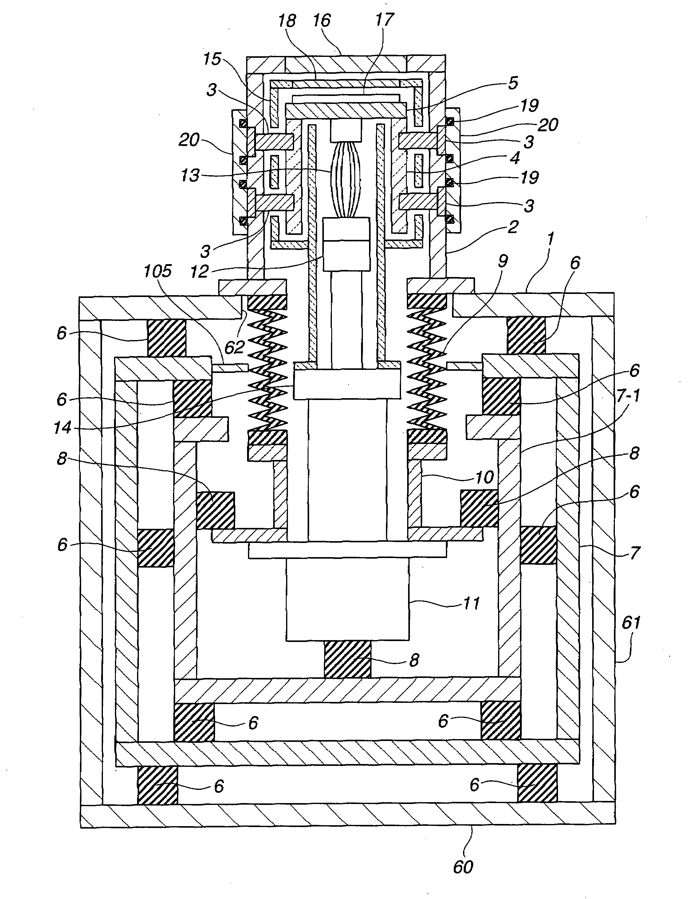
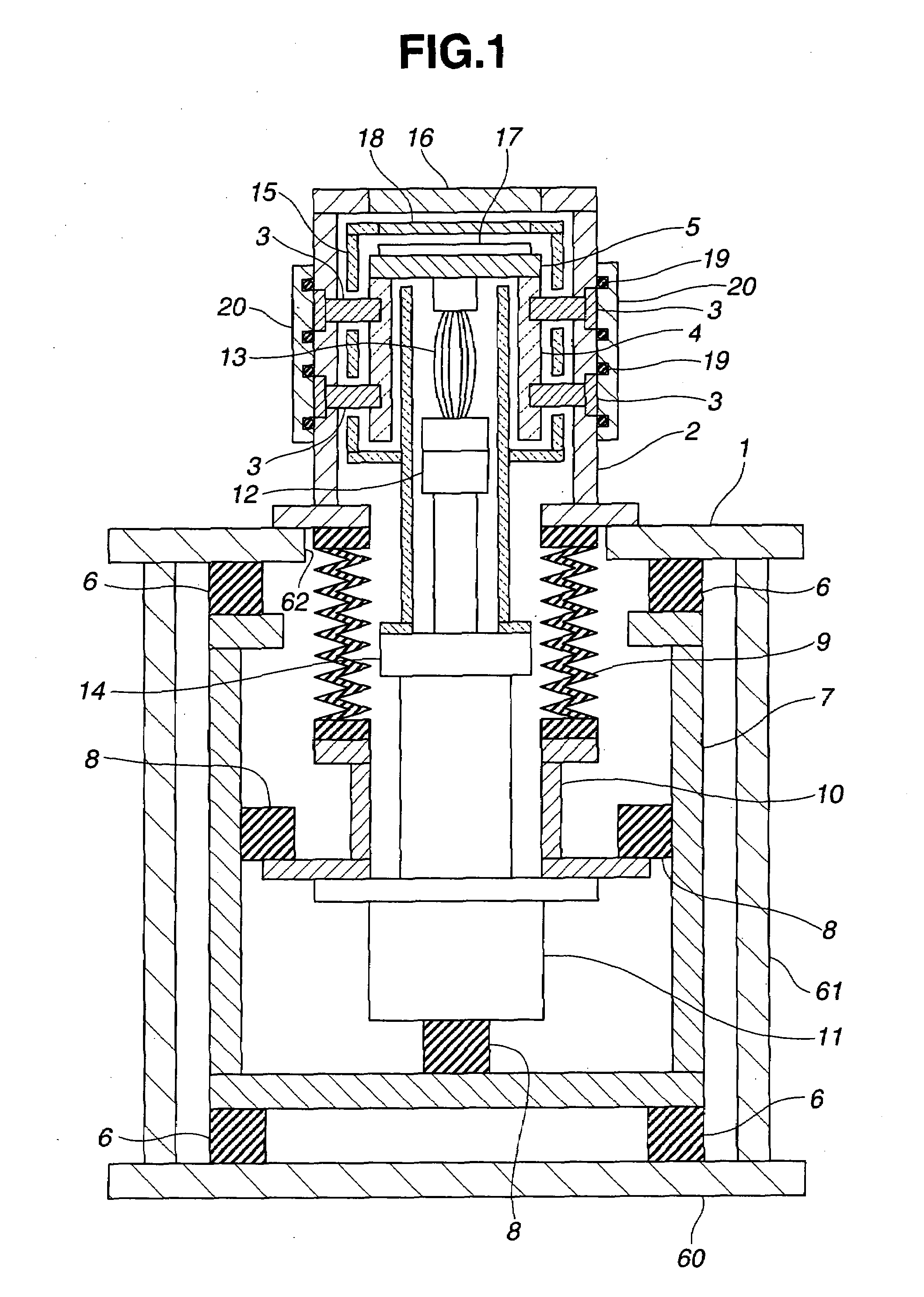
[0028]FIG. 1 is a diagrammatic view, partly in vertical section and partly in side elevation, of a structure of a sample cooling apparatus according to the present invention. As shown in FIG. 1, the sample cooling apparatus includes a vacuum vessel 2 mounted on a housing having a table for forming a measurement reference surface 1 in which a sample holder 5 is disposed to be supported by a thermal insulator 4. Within the housing, a frame 7 is disposed to be supported by first buffers 6, and a refrigerating machine 11 is supported by the frame 7 by means of second buffers 8, while a head of the refrigerating machine 12 is directed to the vacuum vessel 2. The head 12 of the refrigerating machine 11 is connected to the sample holder 5 by means of a flexible thermal conduction member 13.

[0029]The table for forming the measurement reference surface 1 incl...


PUM


Abstract

A sample cooling apparatus capable of cooling and holding samples or wafers at a cryogenic temperature with no vibration or drift with respect to a measurement reference surface is disclosed. In the sample cooling apparatus, a sample holder is arranged in a vacuum vessel mounted on a housing having a table for forming a measurement reference surface to be supported by a thermal insulator. A frame is disposed within the housing to be supported by a first buffer. A refrigerating machine is disposed in the frame to be supported by a second buffer and has a head directed to the vacuum vessel. The cooling head of the refrigerating machine is connected to the sample holder by way of a flexible thermal conduction member.

Description

CROSS REFERENCES TO RELATED APPLICATIONS[0001]This application claims the priority benefit of Japanese Patent Application No. 2006-105586 filed on Apr. 6, 2006.STATEMENT REGARDING FEDERALLY SPONSORED RESEARCH[0002]Not Applicable.BACKGROUND OF THE INVENTION[0003]1. Field of the Invention[0004]The present invention relates to an apparatus for cooling samples or wafers at a cryogenic temperature so as to perform microscopic observation, microspectroscopic analysis, near-field microscopic observation, near-field spectroscopic analysis, and photoconduction characteristic evaluation, or conduction characteristic evaluation.[0005]2. Description of the Related Art[0006]When samples or wafers are cooled at a cryogenic temperature with a refrigerating machine, a vibration of the refrigerating machine as a vibration source propagates to the samples or wafers. As a result, the samples or wafers vibrate or drift with respect to a measurement reference surface, which deteriorates a precision of m...

Claims


Application Information

Patent Timeline
Patent Type & Authority Applications(United States)
IPC IPC(8): F25B9/00F25D19/00
CPCF25D19/006
Inventor NAGAMUNE, YASUSHI
Owner NAT INST OF ADVANCED IND SCI & TECH
Why Eureka
Try Eureka