Substrate processing method and substrate processing apparatus

a substrate and processing method technology, applied in the direction of photomechanical treatment, cleaning using liquids, instruments, etc., can solve the problems of insufficient removal of particles, damage to patterns formed on the surface of substrates, and inability to remove particles in sufficient quantities

Inactive Publication Date: 2007-10-11
DAINIPPON SCREEN MTG CO LTD
View PDF16 Cites 33 Cited by
  • Summary
  • Abstract
  • Description
  • Claims
  • Application Information

AI Technical Summary

Benefits of technology

[0009]The invention has been made in light of the problems described above, and accordingly, an object of the invention is to provide a substrate processing method and a substrate processing apparatus with which it is possible to remove particles adhering to a substrate surface without damaging the substrate.
[0010]According to a first aspect of the present invention, there is provided a substrate processing method of cleaning a substrate, the method comprising: a first step of freezing a liquid film as it is maintained adhering to a surface of the substrate; and a second step of performing upon the surface of the substrate physical cleaning which exerts a physical effect upon the surface of the substrate, chemical cleaning which exerts a chemical effect upon the surface of the substrate, or cleaning which combines the physical cleaning and the chemical cleaning, thereby removing the liquid film which has been processed freezing off from the surface of the substrate.
[0011]According to a second aspe...

Problems solved by technology

By the way, a device which is typically a semiconductor has increasingly finer patterns and more advanced functions and is more and more precise these days, which has lead to a new problem that defects occur in patterns formed on a surface of a substrate during cleaning of the substrate.
However, a problem that the patterns are destroyed has occurred.
On the other hand, when the condition of generating the liquid droplet is adjusted such that the defects do not occur in patt...

Method used


Image

  • Substrate processing method and substrate processing apparatus
  • Substrate processing method and substrate processing apparatus
  • Substrate processing method and substrate processing apparatus

Examples


first embodiment

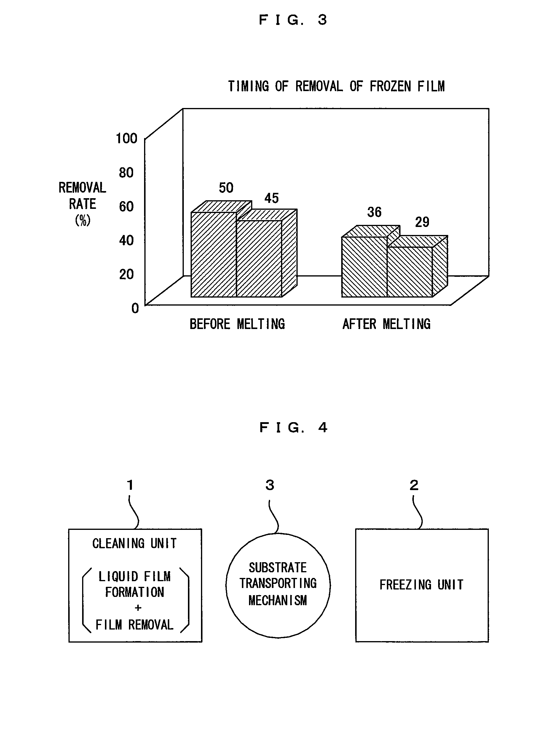
[0058]FIG. 4 is a plan layout diagram of a substrate processing apparatus of a first embodiment of this invention. FIG. 5 is a block diagram showing a control construction of the substrate processing apparatus shown in FIG. 4. In this substrate processing apparatus, a cleaning unit 1 and a freezing unit 2 are arranged while being separated from each other by a specified distance, and a substrate transporting mechanism 3 is arranged between the units 1 and 2. Out of these units, the cleaning unit 1 is a unit which forms a liquid film on a surface of each substrate such as a semiconductor wafer and removes the liquid film after the freezing. The substrate having the liquid film formed on the surface thereof in the cleaning unit 1 is transferred to the freezing unit 2 by the substrate transporting mechanism 3. In the freezing unit 2, a frozen film is formed by freezing the liquid film by applying a freezing process to the substrates. The substrate subjected to the freezing process is t...

second embodiment

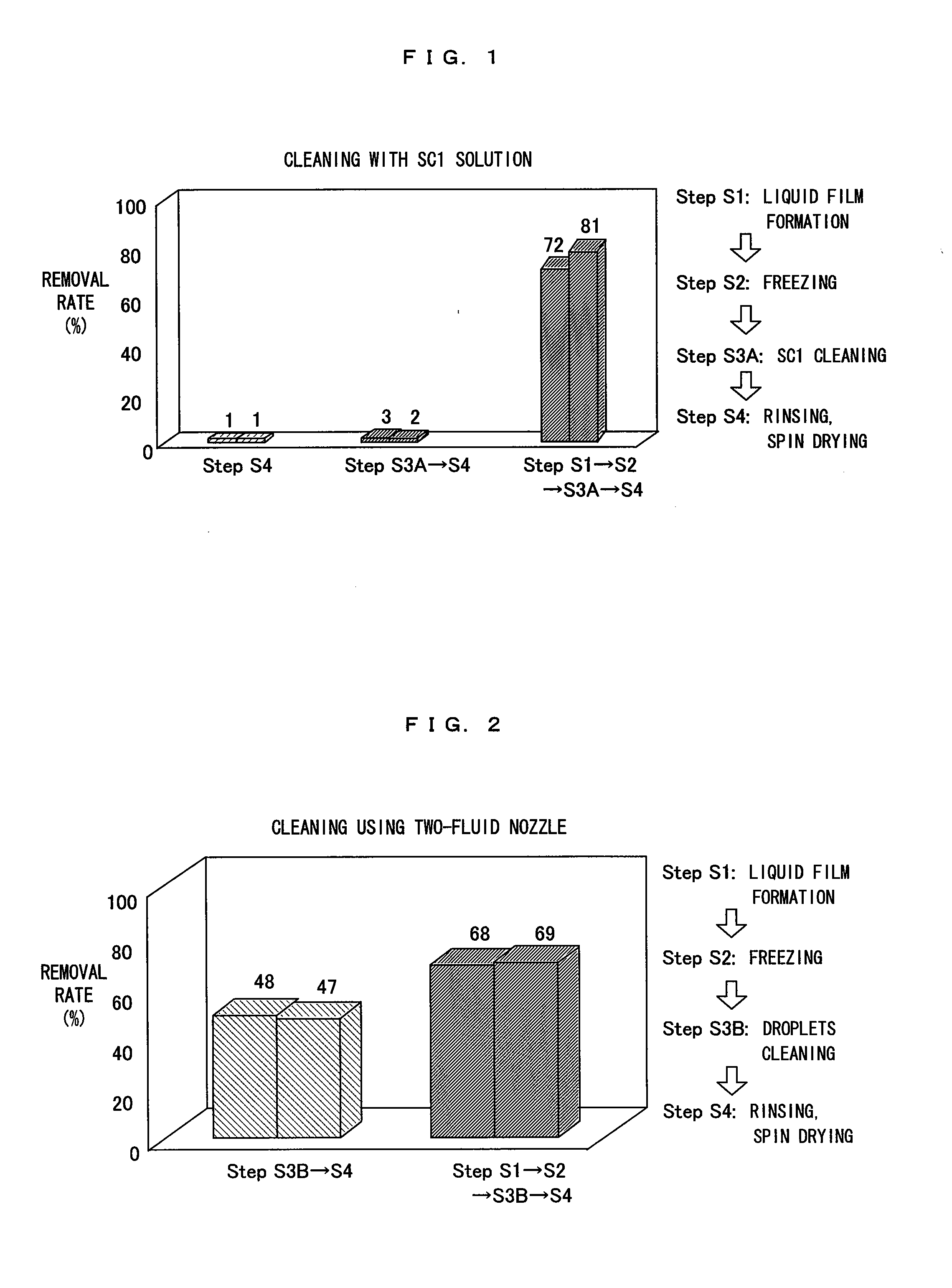
[0085]FIG. 9 is a cross sectional view of the structure of a cleaning unit which is disposed in a substrate processing apparatus according to a second embodiment of the invention. In the first embodiment described above, the SC1 cleaning is executed as the physical and / or the chemical cleaning, and the preprocessing (liquid film formation and freezing the liquid film) prior to the SC1 cleaning to thereby assist the particle removal effect of the SC1 cleaning. However, in this second embodiment, a cleaning with droplets using a two-fluid nozzle (droplets cleaning) is executed as the physical and / or the chemical cleaning, and the preprocessing is executed prior to the droplets cleaning to thereby assist the particle removal effect of the droplets cleaning. A major difference of a cleaning unit 1A which is disposed in the substrate processing apparatus according to the second embodiment from the first embodiment is that a droplet supplier 60 is newly added which supplies droplets to a ...

third embodiment

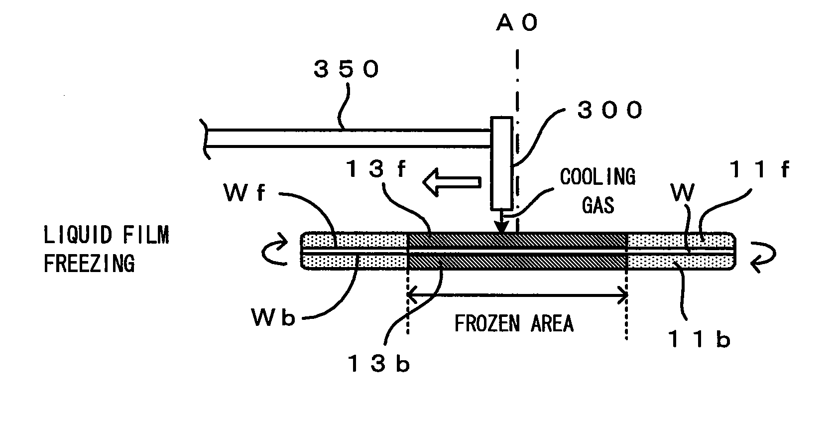
[0097]FIG. 11 is a diagram showing a substrate processing apparatus of a third embodiment of the invention. FIG. 12 is a block diagram showing a control construction of the substrate processing apparatus shown in FIG. 11. This substrate processing apparatus is a single wafer type substrate processing apparatus that is used for the cleaning processes for the purpose of removing contaminants such as particles adhering to a surface Wf of a substrate W such as semiconductor wafer. More specifically, this is an apparatus which forms a liquid film on the substrate surface Wf on which fine patterns are formed, then freezes the liquid film, and then removes the liquid film which has been processed freezing (frozen film) from the substrate surface Wf, that is, the apparatus performs a series of cleaning process (liquid film formation+freezing the liquid film+film removal) to a substrate W.

[0098]This substrate processing apparatus includes a processing chamber 100 which has a processing space...


PUM

PropertyMeasurementUnit
Fractionaaaaaaaaaa
Fractionaaaaaaaaaa
Fractionaaaaaaaaaa

Abstract

A substrate on the surface of which the liquid film is formed in a cleaning unit is transported to a freezing unit by a substrate transporting mechanism. The liquid film is frozen in the freezing unit and the volume of the liquid film increases. Accordingly, adhesive forces between the substrate and the particles are reduced and the particles even come to separate from the substrate surface. Then the substrate which has been processed freezing is transported from the freezing unit to the cleaning unit again by the substrate transporting mechanism. In the cleaning unit, a physical and/or chemical cleaning is executed to the substrate, and the frozen film is removed from the substrate surface. Thus, the liquid film formation and the freezing of the liquid film is performed as a preprocessing of the physical and/or chemical cleaning in this way, whereby the particles are removed from the substrate surface efficiently.

Description

CROSS REFERENCE TO RELATED APPLICATION[0001]The disclosure of Japanese Patent Applications No. 2006-108801 filed Apr. 11, 2006 and No. 2006-248181 filed Sep. 13, 2006 including specification, drawings and claims is incorporated herein by reference in its entirety.BACKGROUND OF THE INVENTION[0002]1. Field of the Invention[0003]The present invention relates to a substrate processing apparatus for and a substrate processing method of cleaning substrates of various types (hereinafter called simply “substrates”) such as semiconductor wafers, glass substrates for photomasks, glass substrates for liquid crystal displays, glass substrates for plasma displays and substrates for optical discs.[0004]2. Description of the Related Art[0005]Manufacturing steps for electronic components such as semiconductor devices and liquid crystal displays include a step of repeating film deposition, etching and otherwise appropriate processing on a surface of a substrate to thereby form fine patterns. As the ...

Claims


Application Information

Patent Timeline
IPC IPC(8): B08B7/00B08B3/00
CPCC03C23/0075G03F1/82H01L21/02057H01L21/67109H01L21/67051H01L21/67057H01L21/67028H01L21/304H01L21/02
Inventor FUJIWARA, NAOZUMIMIYA, KATSUHIKOIZUMI, AKIRA
Owner DAINIPPON SCREEN MTG CO LTD
Why Eureka
Try Eureka