

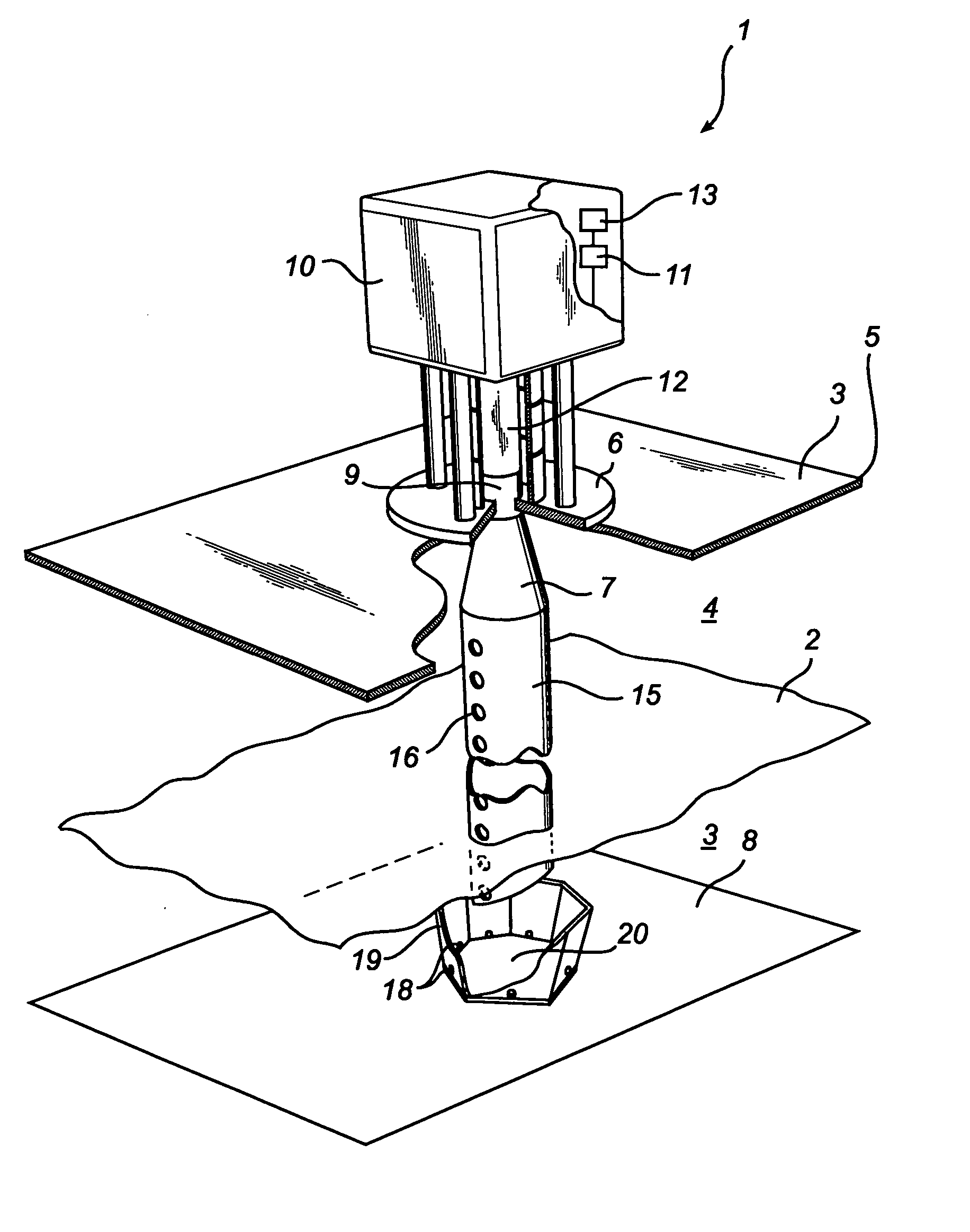
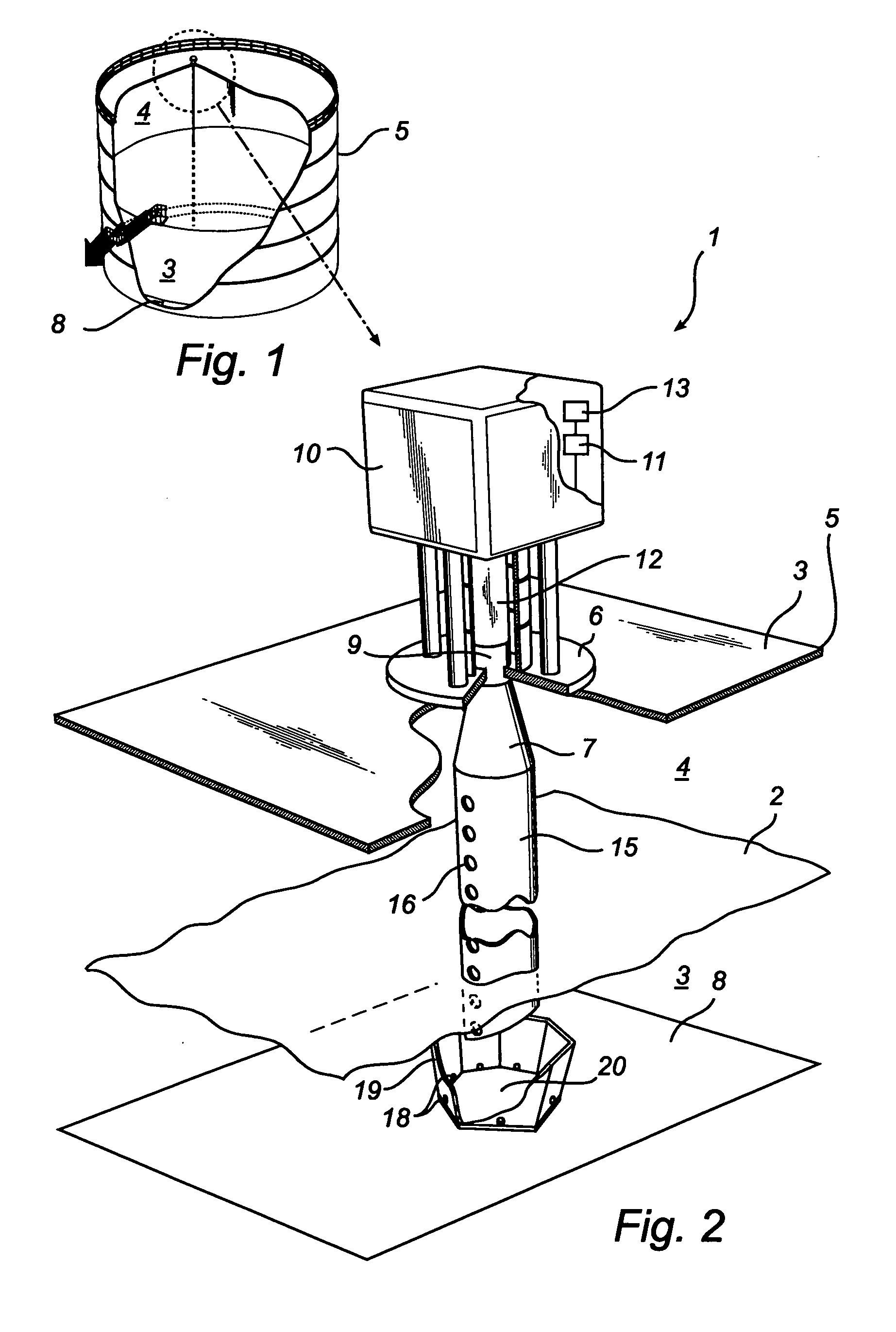
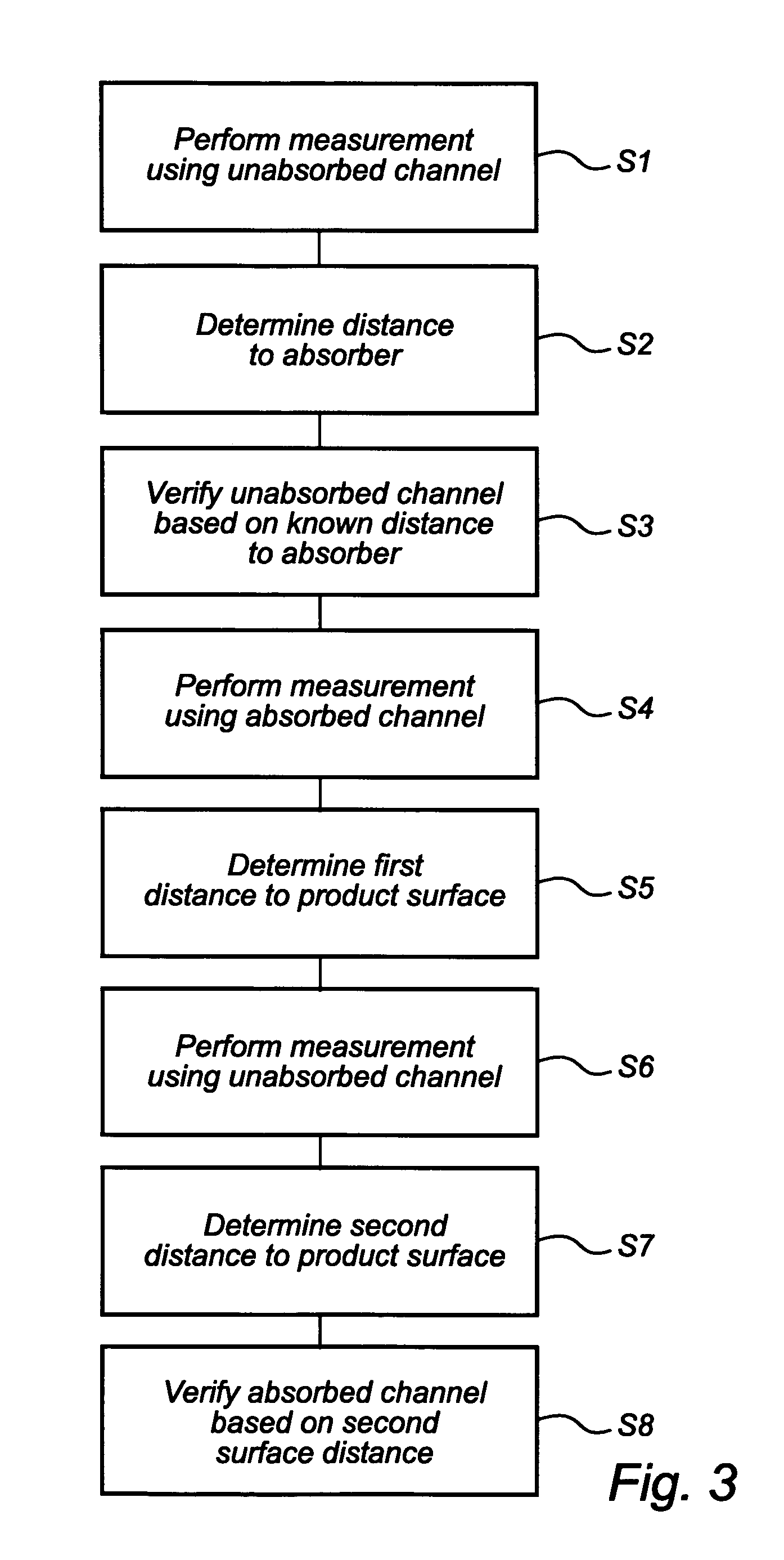
Radar level gauging system
a technology of gauging system and radar, applied in the direction of using reradiation, liquid/fluent solid measurement, antenna, etc., can solve the problems of affecting the surface reflection, affecting the product level, and relative strong reflection,
- Summary
- Abstract
- Description
- Claims
- Application Information
AI Technical Summary
Benefits of technology
Problems solved by technology
Method used
Image

Examples
first embodiment
[0058] an absorber 120 according to the invention is shown in FIG. 8. The absorber here comprises a plate 121 of a material that absorbs electromagnetic energy, in particular microwave energy. Examples of such materials include plastic materials such as PTFE, and silicon rubber, e.g. Eccosorb ® MFS. This material can optionally be coated by a protective cover, e.g. of high density polyethylene. In order to avoid any reflection in the interface between tank content and absorber material, the plate is formed to have a cross section in a plane normal to a direction of incidence of microwaves that decreases with the vertical position, i.e. towards the antenna. In other words, the cross section is smaller in a position closer to the antenna, and then increases to become larger closer to the bottom. In the illustrated example, this is accomplished by forming the upper surface of the plate as a pattern of spikes, here standing pyramids 122. The cross section discussed is then formed by the...
second embodiment
[0061] an absorber 220 according to the invention is shown in FIG. 9. In this case, the absorber comprises one or several metal sheets 221 bent to form a pointed ridge 222. Waves having a polarization coinciding with the longitudinal extension of the ridge will be reflected, while waves having a polarization perpendicular to the ridges will be reflected in the sloping sides of the ridge. The curvature of t3eh ridges, and the slope of the sides of the ridges are chosen such that waves reflected by these sides will not enter the opening of the tube, and will thus not reach the antenna. Depending on the required slope, it may be necessary to provide several bent metal sheets next to each other, in order to cover the entire projection of the tube opening.
[0062] A further embodiment of an absorber 320 is shown in FIG. 10. Here, similar to the embodiment in FIG. 8, the absorber comprises a plate 321 of microwave absorbing material formed with pyramids. In this case, the plate is provided ...
PUM
 Abstract
Description
Claims
Application Information