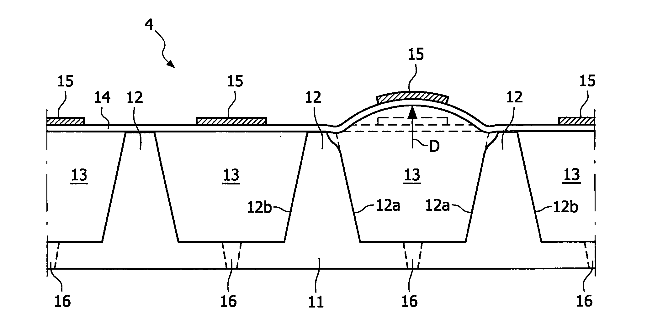
[0004] It is an object of the present invention is to provide a relatively efficient printhead. This object can be achieved by providing a printhead wherein the wall and the converter are adapted for mutual cooperation, such that, based on this cooperation, actuation of the converter of an ink chamber leads to buckling of the converter. Actuation of the converter will elastically bend (a part of) the deformable wall outwardly, which causes the converter to buckle upwardly, thereby (temporarily) increasing the volume of the ink chamber. According to the present invention, it has been found that this (reversible) buckling effect of the converter significantly increases the efficiency of the converter and hence of the functioning of the printhead. More particularly, due to this buckling effect the presence of a relatively thick passive (
inert) intermediate layer, such as a conventional (ceramic) closure plate, onto which the converter is superimposed is no longer required and can therefore be omitted. Omission, or at least a reduction of the thickness of a conventional passive layer results in a relatively
low voltage of less than 10
Volt being required to actuate the converter in a satisfying manner to cause a controlled volume change of the ink chamber(s). Applying relatively low voltages to actuate the converter leads to a corresponding saving in energy, and hence a relatively efficient printhead for an inkjet printer. A further
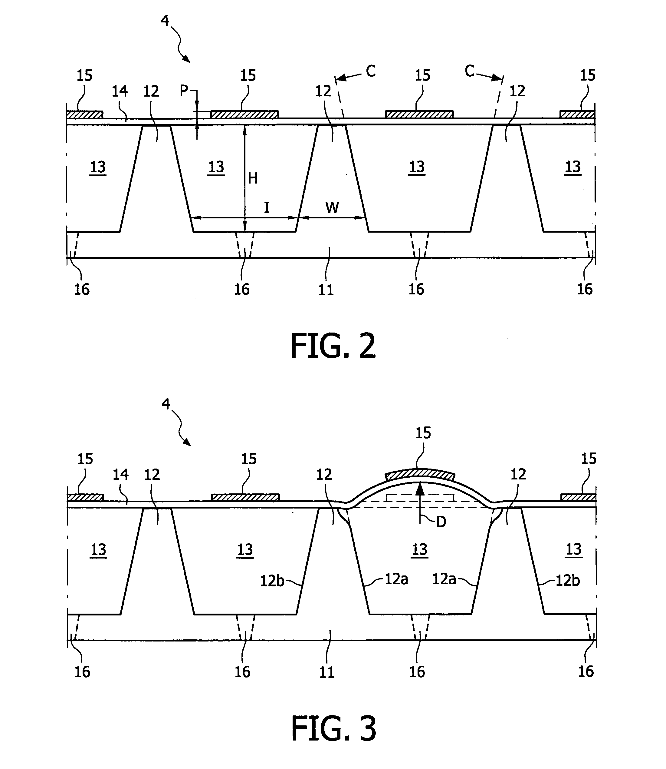
advantage of the printhead is that the wall(s) will be partially deformed upon actuation of the converter. By allowing merely a (substantial) partial, and preferably a (location) selective deformation of the wall, cross-talk between adjacent ink chambers can be counteracted in a relatively efficient and satisfying manner. Advantageously, the wall comprises a first wall side (partially) defining a first chamber and a second wall side, opposite to the first wall side, said second wall side (partially) defining a second, neighboring chamber, wherein the walls are deformable, such that actuation of the converter of the first chamber leads to a deformation of the wall, the deformation of the first wall side is being substantially larger than the deformation of the second wall side. Although the deformation behavior of the wall can be optimized for the printhead to allow merely a partial deformation upon the actuation of the converter, it is recognized that frequently it will not be possible to prevent actuation of a converter to produce a (slight) volume change in an adjacent chamber. This is because it is difficult to achieve both a full power closure between adjacent
converters and also prevent stretching of the chambers. However, by optimizing the deformation behavior of the wall, being determined by the material, the shape and the
dimensioning of the wall and the like, cross-talk between adjacent ink chambers can be minimized, and can be reduced to less than one percent.
[0005] In a preferred embodiment of the printhead according to the present invention, the wall has a tapered configuration. According to this embodiment the first wall side and the second wall side of the wall are oriented in a non-parallel orientation with respect to each other. This leads to an improved storage capacity of
elastic energy within the wall and to an advantageous wall deformation and to an efficient buckling of the converter upon actuation of the converter.
[0006] In a preferred embodiment, the wall is made of a material having a Young's modulus (E modulus) smaller than 60 GPa, preferably less than 30 Gpa, and more preferably around 10 GPa. In this embodiment, the wall between adjacent ink chambers is made from a relatively easily deformable (elastic) material with a relatively good shape
recovery ability. This means that the wall can be made relatively thick without restrictions in deformability becoming an issue. An allowed robustness of the walls facilitates a less critical and a relatively simple manufacturing of the printhead according to the present invention.
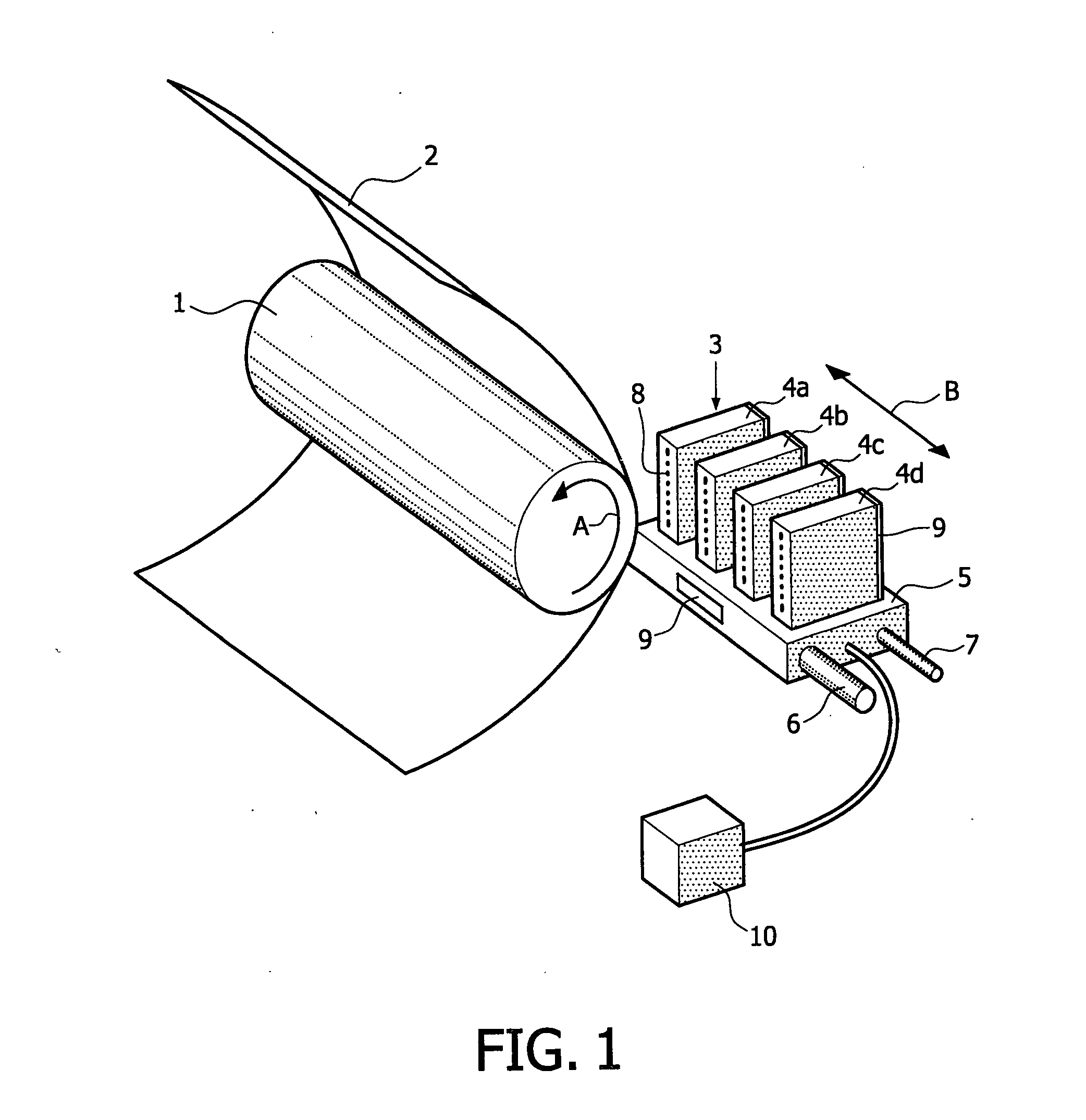
[0008] In a preferred embodiment the printhead comprises a carrier plate provided with at least one wall, wherein the carrier plate and the one wall are made of substantial similar materials. In this embodiment, the chambers and walls may easily be made by milling the chambers from a carbon element, which automatically produces a carbon wall between the chambers. When selecting a certain type of carbon, the wall thickness and height requirements may be determined based on experiments or a model that may be applied in accordance with the present invention.
[0010] The invention also relates to an inkjet printer comprising at least one printhead as described above. Such a printhead may be applied without producing undesirable print artefacts in a printed image.

