Laminographic system for 3D imaging and inspection

a 3d imaging and inspection technology, applied in the field of 3d imaging and inspection laser systems, can solve the problems of inability to build such a giant gantry, and inability to achieve the desired or optimal way of detecting, etc., to achieve the effect of improving the detection criteria

Inactive Publication Date: 2007-10-11
SINGH SATPAL
View PDF12 Cites 54 Cited by
  • Summary
  • Abstract
  • Description
  • Claims
  • Application Information

AI Technical Summary

Benefits of technology

[0021] In one embodiment of the invention, the object or bag to be scanned is placed on a conveyor belt that moves through a tunnel which houses the x-ray source and detectors. The radiation from a x-ray source is shaped by a collimator into several radiation beams that are flat and fan shaped. Each such fan beam propagates across the tunnel and is received by it associated set of detectors, the detectors are “L” shaped linear arrays. The orientation of the fan beams is such that they diverge outwards from the x-ray source and when the object is translated through the tunnel, it gets scanned at different angles by these several radiation beams. The scanned

Problems solved by technology

The existing 3D methods employed for baggage screening use the methods of Computed Tomography (CT) which are very slow, very costly, very bulky.
The use of prescanning by conventional x-ray scanners that generate 2D images is employed to select

Method used


Image

  • Laminographic system for 3D imaging and inspection
  • Laminographic system for 3D imaging and inspection
  • Laminographic system for 3D imaging and inspection

Examples


Embodiment Construction

[0030] In describing the preferred embodiment and its alternatives, specific terminology will be used for the sake of clarity. However, the invention is not limited to the specific terms so used, and it should be understood that each specific term includes all its technical equivalents which operate in a similar manner to accomplish similar purpose.

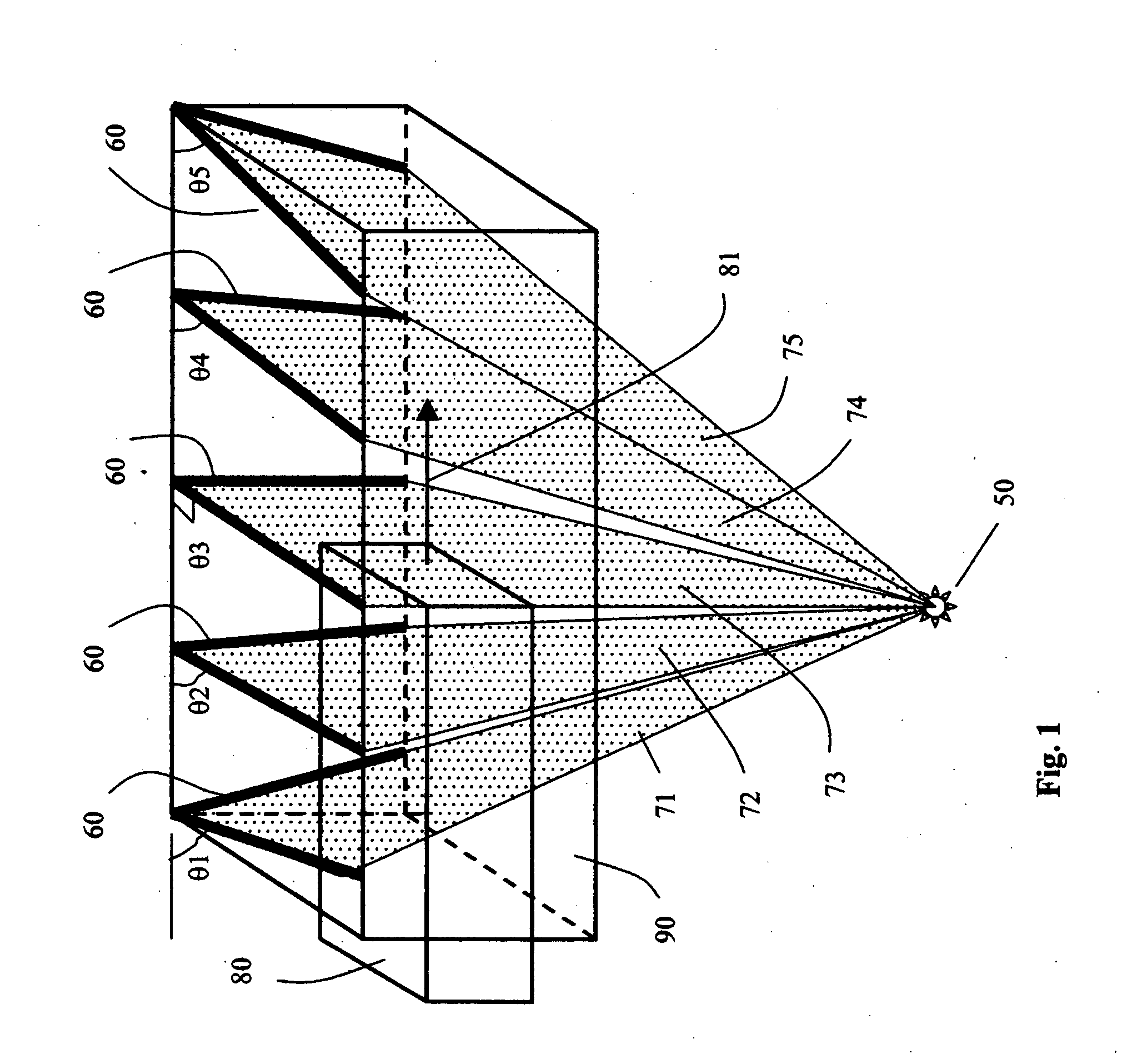
[0031]FIG. 1 shows a preferred embodiment of the present invention as used for baggage screening. For the sake of clarity in the drawings, the ordinary details relating to the mechanics of the system have been omitted as these are well known to a person skilled in the field.

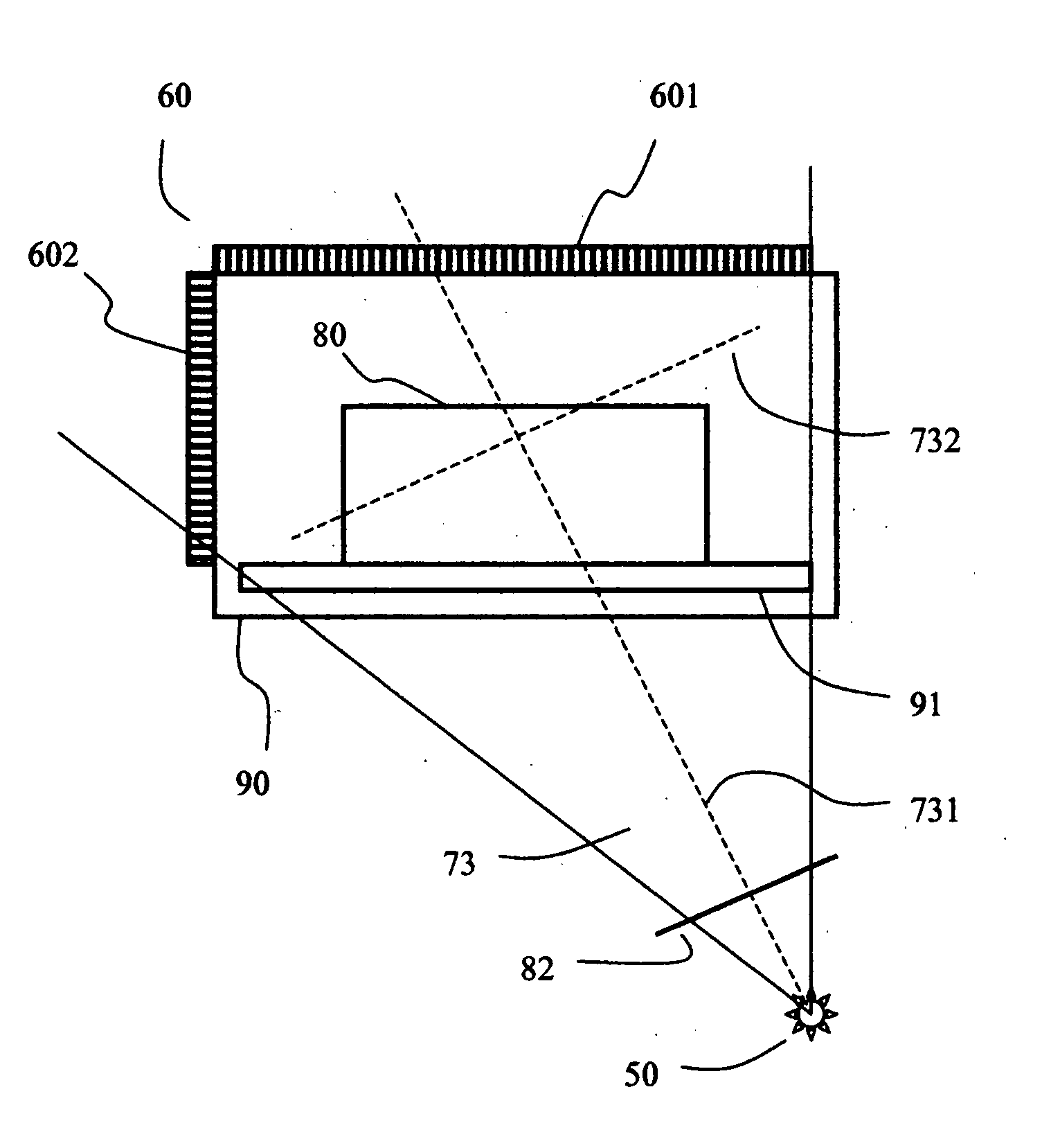
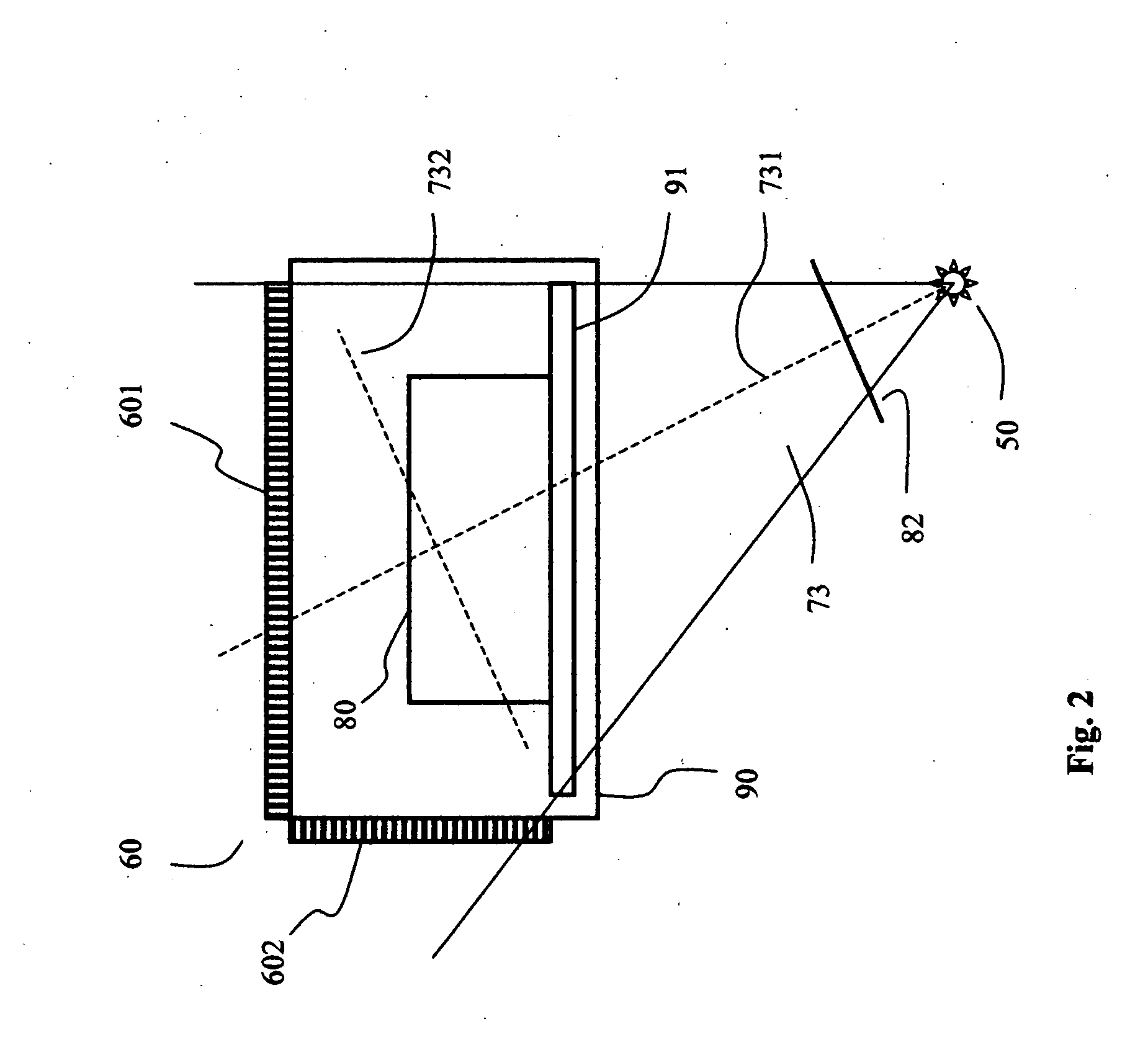
[0032] As shown in FIG. 1, an object or bag 80 is transported through a tunnel 90 in the direction of the arrow 81. Not shown in this figure to avoid the clutter are the conveyor belt, the motors and the transport mechanism and other details which are well known to a person skilled in the field.

[0033] As illustrated in FIG. 1, when the object moves through the tunne...


PUM


Abstract

A digital Laminographic or Tomosynthesis method is described for use in the detection of explosives concealed in baggage. The method uses at least one source of x-ray and at least two sets of detectors, preferably more to generate 3D images of high detail. The data from the detectors can be simply time delayed and summed up to generate high definition image of layers through the bag. This leads to very high speed of 3D imaging, the same speed as in regular x-ray scanners. In addition, there is no rotating gantry, the systems is simple, compact, relatively inexpensive, and can be used to generate 3D images of large shipping containers.

Description

BACKGROUND OF THE INVENTION [0001] 1. Field of the Invention [0002] This invention relates to the use of digital Laminography for 3D imaging and inspection of baggage or objects, the technique of Laminography is also described alternatively as Tomosynthesis or Computed Tomography from limited projections. This invention is suited for automated systems used for the detection of explosives in baggage, and for 3D imaging for medical and non-medical applications. [0003] 2. Description of the Related Art [0004] Most of the baggage screeners in use today generate a shadow image by interposing a baggage between a x-ray source and a linear array of radiation detectors, and translating or scanning the baggage over the said linear detector. This method generates a 2 D image from which it is difficult to detect for explosive and more so if the explosives are disposed off in the form of thin sheets, this problem is well known to the people skilled in the field. [0005] To overcome the above draw...

Claims


Application Information

Patent Timeline
IPC IPC(8): G01N23/04
CPCG01N2223/419G01N23/046G01N23/10G01N23/044
Inventor SINGH, SATPAL
Owner SINGH SATPAL
Why Eureka
Try Eureka