Grating apodization technique for diffused optical waveguides

a technology of optical waveguides and grating apods, which is applied in the direction of optical waveguide light guides, instruments, optics, etc., can solve the problems of requiring a very precise and therefore costly fabrication technique, and affecting the reflection and transmission filter response characteristic of the waveguid

Active Publication Date: 2007-10-11
NORTHROP GRUMMAN SYST CORP
View PDF3 Cites 14 Cited by
  • Summary
  • Abstract
  • Description
  • Claims
  • Application Information

AI Technical Summary

Benefits of technology

[0010] It will be appreciated from the foregoing summary that the present invention represents a significant advance in the field of optical channel waveguides with Bragg-type reflection gratings. In particular, the invention provides a greatly improved tech

Problems solved by technology

Reflections from the grating elements may interfere constructively or destructively, affecting the reflection and transmission filter response characteristic of the waveguide.
This requires a very pre

Method used


Image

  • Grating apodization technique for diffused optical waveguides
  • Grating apodization technique for diffused optical waveguides
  • Grating apodization technique for diffused optical waveguides

Examples


Embodiment Construction

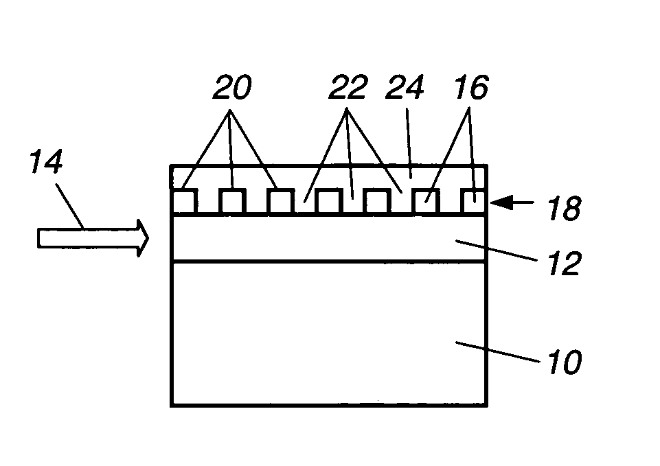
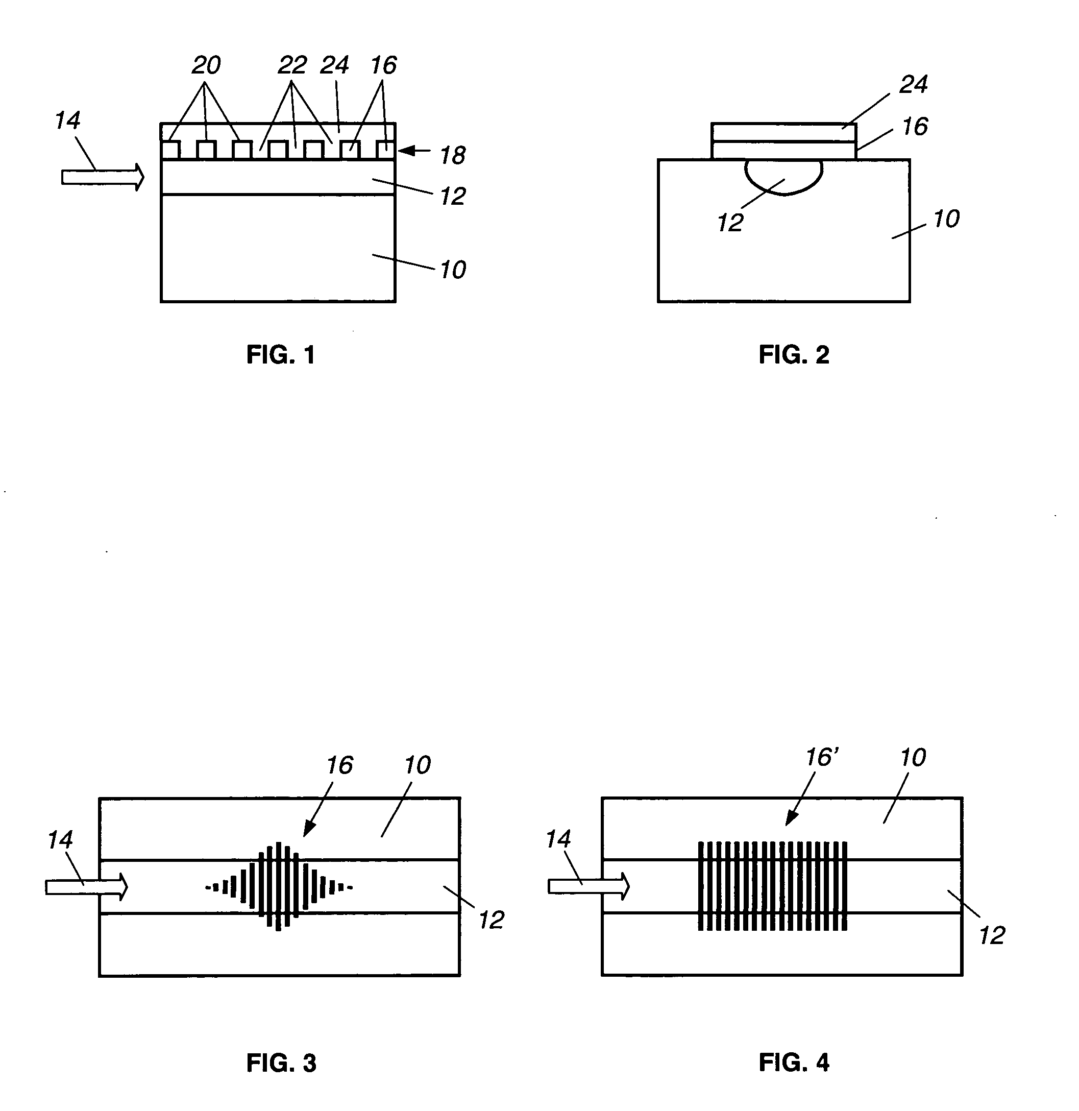
[0018] As shown in the drawings for purposes of illustration, the present invention is concerned with a technique for forming an apodized optical grating on or in an optical channel waveguide. In accordance with the invention, the grating is apodized by varying the lengths of individual elements of the grating disposed across the width of the optical channel. By this means, all other dimensional parameters of the grating may be maintained constant, including the duty cycle, the grating depth, and the grating elemental length in the principal direction of light propagation.

[0019] In a preferred embodiment of the invention, and as shown in FIGS. 1-3, an optical channel waveguide is formed in a dielectric substrate, indicated by reference numeral 10, of a material such as lithium niobate (LNO). As best viewed in FIG. 2, the waveguide is formed by a channel region 12 into which a metal, such as titanium (Ti) is diffused. Light launched into the waveguide will be guided through the chan...


PUM


Abstract

An optical channel waveguide having a reflection grating and a related method for its fabrication. The grating is apodized to provide a desired reflection or transmission spectral characteristic, by varying the grating width along the length of the grating in the direction of light propagation. The grating has multiple parallel elements extending across the waveguide channel width, and apodization is effected by appropriate selection of the width of each element relative to the width of the channel, without varying the grating duty cycle or other parameters.

Description

[0001] This invention was made with Government support under Contract No. N66001-02-C-8020 awarded by the Department of Defense. The Government has certain rights in this invention.BACKGROUND OF THE INVENTION [0002] This invention relates generally to optical channel waveguides and, more particularly, for techniques for obtaining a desired optical reflection and transmission filter response in optical channel waveguides. Optical waveguides have a variety of both military and commercial applications, such as in optical signal processing, optical networking and related communication systems. In processing optical signals, there is frequently a need to provide filtering function and one well known way of achieving this is an optical grating, such as a Bragg grating, integrated into a waveguide. A grating is a periodic structure either formed in the surface of a waveguide or embedded in the volume of the waveguide as variations in refractive index. Regardless of its form, the grating pr...

Claims


Application Information

Patent Timeline
IPC IPC(8): G02B6/34G02B6/124G02B6/134G02B6/136
CPCG02B6/124G02B6/136G02B6/1342
Inventor DAVIS, RICHARD L.HO, JAMES G.SHAH, AKHIL R.JUNG, THOMAS J.LAM, TERRANCE T.
Owner NORTHROP GRUMMAN SYST CORP
Why Eureka
Try Eureka