Closed Loop Catheter Photopolymerization System and Method of Treating a Vascular Condition

a closed loop catheter and photopolymerization technology, which is applied in the field of biomedical systems for treating vascular conditions, can solve the problems of unfavorable patient safety, unsatisfactory treatment effect, and large crossing profile of catheters,

Inactive Publication Date: 2007-10-11
MEDTRONIC VASCULAR INC
View PDF12 Cites 69 Cited by
  • Summary
  • Abstract
  • Description
  • Claims
  • Application Information

AI Technical Summary

Problems solved by technology

Because a typical dual occlusion catheter requires a separate inflation lumen for each balloon, the catheter is bulky, having an undesirably large crossing profile.
If left in place, the guidewire produces a shadow on the wall of the vessel, resulting in incomplete coverage of the vessel with a polymer coating.
The additional step of withdrawing the guidewire adds to the time required to perform the photopolymerization procedure, posing some risk that the vessel may be damaged or other complications may occur.

Method used


Image

  • Closed Loop Catheter Photopolymerization System and Method of Treating a Vascular Condition
  • Closed Loop Catheter Photopolymerization System and Method of Treating a Vascular Condition
  • Closed Loop Catheter Photopolymerization System and Method of Treating a Vascular Condition

Examples


Embodiment Construction

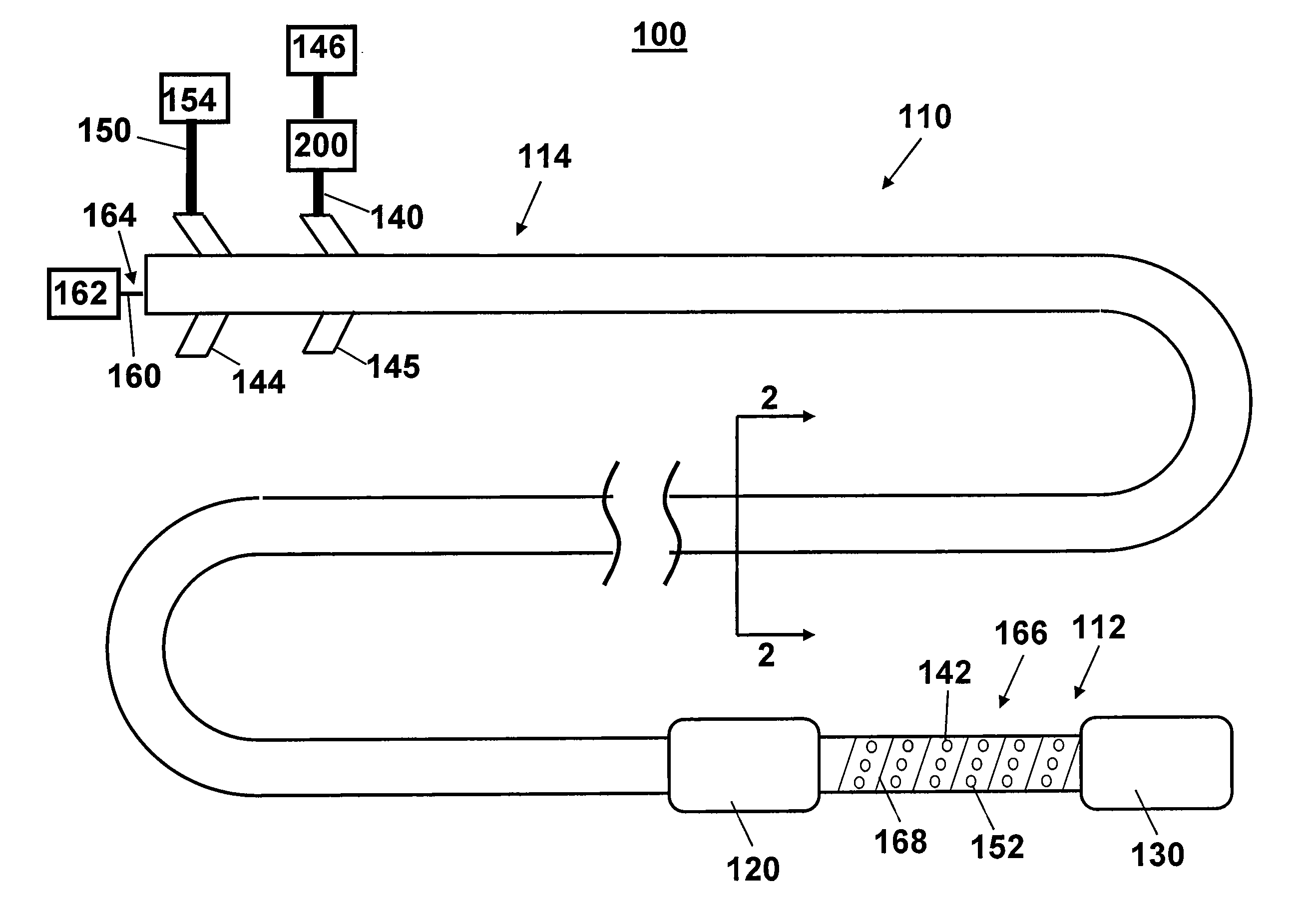
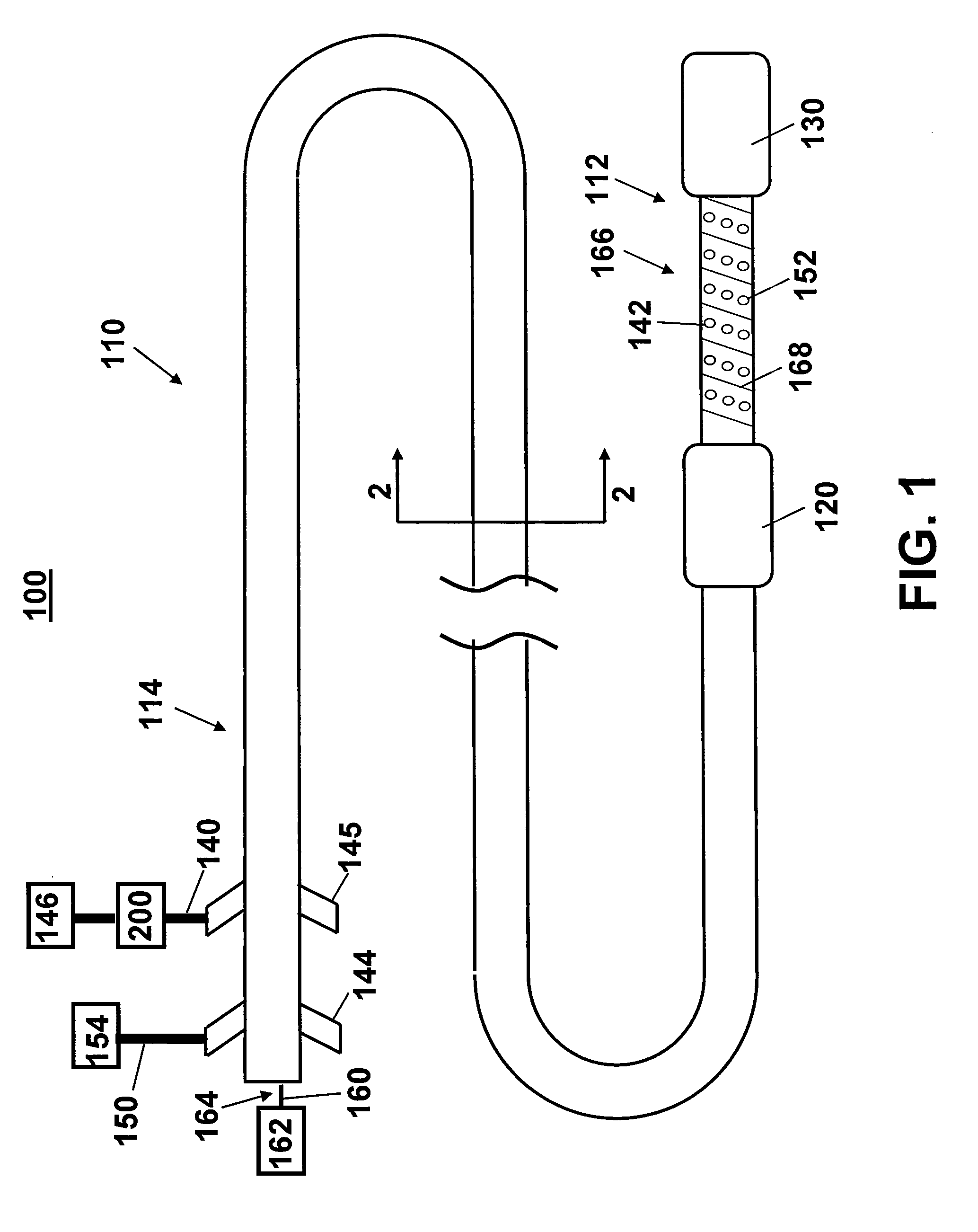
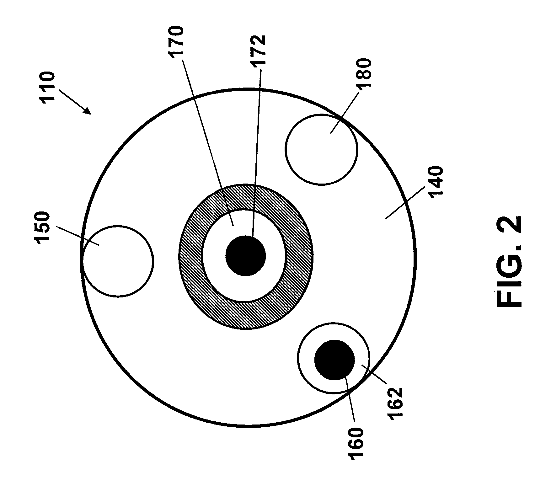
[0015] One aspect of the present invention is a photopolymerization system for treating a vascular condition. The system, illustrated in FIGS. 1 and 2 at 100, includes a catheter 110 having a proximal inflatable member 120, a distal inflatable member 130, a fluid delivery lumen 140, and a fluid drainage lumen 150. Fluid delivery lumen 140 includes at least one delivery port 142 and the fluid drainage lumen 150 includes at least one drainage port 152. Ports 142, 152 are positioned between the proximal inflatable member 120 and the distal inflatable member 130. A light emission member 160 is positioned adjacent the catheter 110.

[0016] In one embodiment, light emission member 160 is an optical fiber operably connected to a light source 162 at a proximal portion 164 and abraded at a distal portion 166. Proximal portion 164 is substantially straight along the length of catheter 110 terminating adjacent a connecter arm of a luer 144. Light is transmitted from the light source 162 through...


PUM


Abstract

A photopolymerization system includes a catheter having a proximal inflatable member, a distal inflatable member, a fluid delivery lumen, and a fluid drainage lumen. The fluid delivery lumen includes at least one delivery port and the fluid drainage lumen at least one drainage port. The ports are positioned between the proximal inflatable member and the distal inflatable member. A light emission member is positioned adjacent the catheter. In a method of treating a vascular condition, the catheter is delivered to a treatment site within a vessel. The first and second inflatable members are expanded to form an enclosed treatment space within the vessel. Fluid is delivered to the treatment space through fluid delivery lumen. Excess fluid is removed from the treatment space through the fluid drainage lumen. The treatment space is exposed to light. A portion of the fluid is polymerized within the treatment space upon exposure to the light.

Description

TECHNICAL FIELD OF THE INVENTION [0001] This invention relates generally to biomedical systems for treating vascular conditions. More specifically, the invention relates to a closed loop catheter photopolymerization system and method of treating a vascular condition. BACKGROUND OF THE INVENTION [0002] Photopolymerization, i.e., polymerization induced by light, is used to convert a liquid monomer or macromer to a polymer using visible or ultraviolet radiation. Some types of cross-linked hydrophilic polymers known as hydrogels may be formed in vivo using photopolymerization. These hydrogels exhibit good biocompatibility, making them attractive materials for use in a variety of biomedical applications. [0003] Formation of photopolymerized hydrogels in vivo can be accomplished using bulk or interfacial photopolymerization. In bulk photopolymerization, a photoinitiator is dissolved in a hydrogel precursor (prepolymer) solution. A photoinitiator is a material that has a high absorption at...

Claims


Application Information

Patent Timeline
Patent Type & Authority Applications(United States)
IPC IPC(8): A61K31/74A61F2/00A61F2/958
CPCA61B17/12022A61B17/12045A61B2017/12127A61B2017/005A61B2017/1205A61B17/12136
Inventor DOTY, DAVID R.
Owner MEDTRONIC VASCULAR INC
Why Eureka
Try Eureka