
Ultrasonic diagnostic apparatus

Inactive Publication Date: 2007-10-11
OLYMPUS CORP
View PDF6 Cites 30 Cited by
  • Summary
  • Abstract
  • Description
  • Claims
  • Application Information

AI Technical Summary

Benefits of technology

[0037] As the 3D image is formed through detection not only of the position on the scan plane but also its orientation, the orientation of the radial scan plane changes accompanied with the change in the orientation of the ultrasonic scan plane. This makes it possible to form the 3D guide image further accurately. Therefore, the operator is allowed to accurately observe the interest region with the 3D guide image even if the angle of the scan plane of the ultrasonic endoscope is varied around the interest region while viewing the 3D guide images.
[0047] According to the twenty-second invention, the sample points on the surface of the body cavity may be accurately designated under the visual field of optical image, thus forming accurate guide images.

Problems solved by technology

Therefore, the guide image is considered as being insufficient to function in guiding the position under observation with the ultrasonic image.
However, the disclosure fails to clarify how the anatomical graphical image is created.
Accordingly, the aforementioned apparatus is still insufficient to provide the usable guide image.

Method used


Image

  • Ultrasonic diagnostic apparatus
  • Ultrasonic diagnostic apparatus
  • Ultrasonic diagnostic apparatus

Examples


embodiment 1

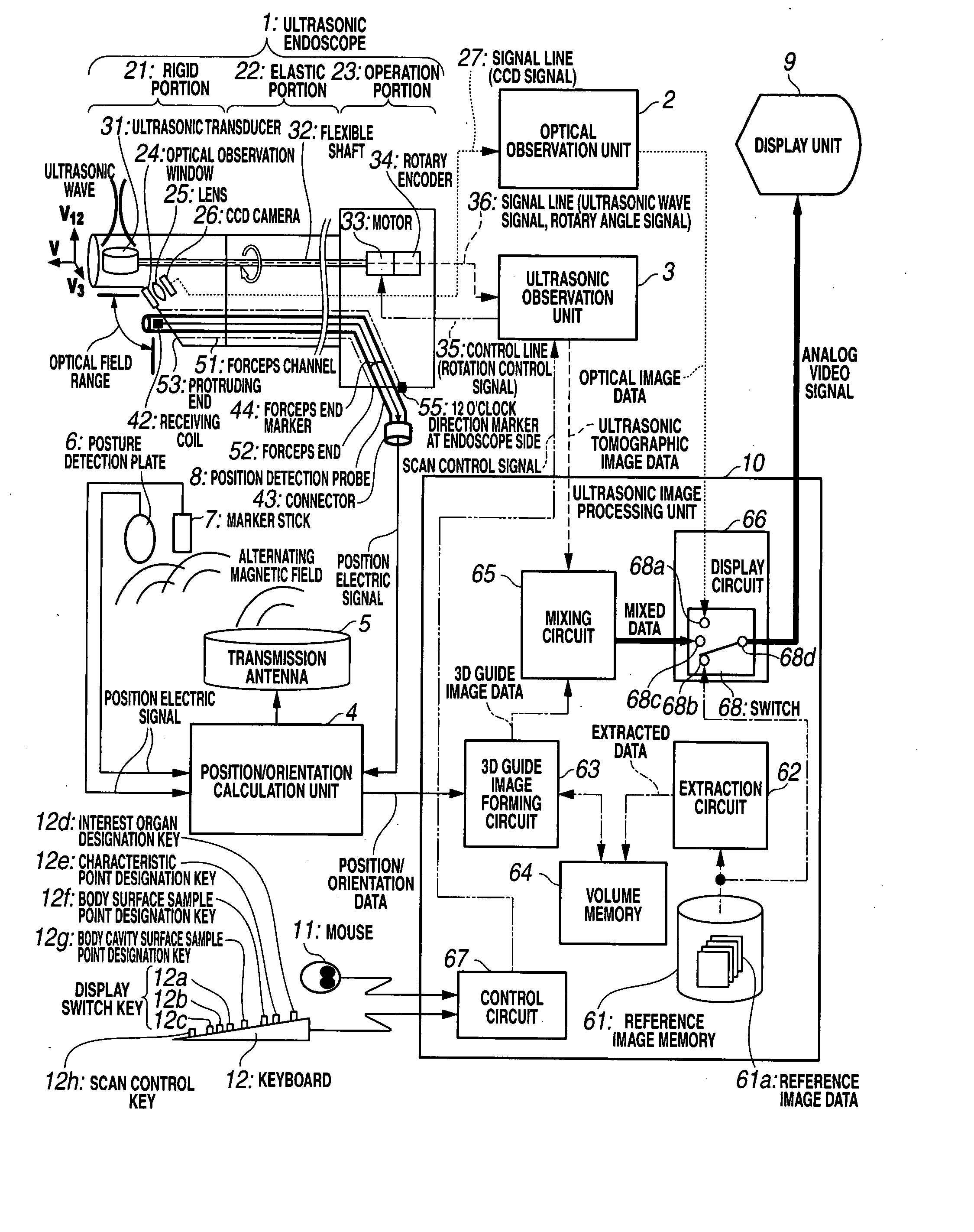
[0072] FIGS. 1 to 20 show embodiment 1 according to the present invention. FIG. 1 is a block diagram showing a configuration of an ultrasonic diagnostic apparatus.

[0073] An ultrasonic diagnostic apparatus of embodiment 1 includes an ultrasonic endoscope 1 as the ultrasonic probe, an optical observation unit 2, an ultrasonic observation unit 3 serving as ultrasonic tomographic image forming means, a position orientation calculation unit 4 serving as detection means, a transmission antenna 5, a posture detection plate 6 serving as body surface sample point position detection means and posture detection means, a marker stick 7 serving as body surface sample point position detection means, a position detection probe 8, a display unit 9 serving as display means, an ultrasonic image processing unit 10, a mouse 11 serving as interest region designation means, and a keyboard 12 serving as interest region designation means, which are electrically coupled with one another via signal lines to...

embodiment 2

[0310]FIGS. 21 and 22 show embodiment 2 according to the present invention. FIG. 21 is a block diagram showing the configuration of the ultrasonic image processing unit connected to the external unit.

[0311] The same components of embodiment 2 as those of embodiment 1 will be designated with the same reference numerals and explanation thereof, thus, will be omitted. The different feature will only be described hereinafter.

[0312] The ultrasonic image processing unit 10 of the present embodiment is formed by adding a communication circuit 69 serving as the communication means to the ultrasonic image processing unit 10 of embodiment 1 as shown in FIG. 1. The communication circuit 69 includes a communication modem that allows the high speed communication of a large volume data.

[0313] The communication circuit 69 is connected to the reference image memory 61 and the control circuit 67 for controlling the communication circuit 69.

[0314] The communication circuit 69 is further connected...

embodiment 3

[0334]FIG. 23 is a view of embodiment 3 according to the present invention showing a block diagram of the configuration of the ultrasonic diagnostic apparatus.

[0335] In embodiment 3, the same components as those shown in embodiments 1 and 2 will be designated with the same reference numerals, and the explanations thereof will be omitted. Only the different features will be described hereinafter.

[0336] The ultrasonic diagnostic apparatus of embodiment 3 is different from the one described in embodiment 1 shown in FIG. 1 in the points as described below.

[0337] The ultrasonic diagnostic apparatus of embodiment 1 employs the ultrasonic endoscope of mechanical radial scan type, which is provided with the flexible shaft 32 for the flexible portion 22, and the motor 33 and the rotary encoder 34 for the operation portion 23. The ultrasonic diagnostic apparatus of embodiment 3 employs the ultrasonic endoscope 1 of electronic radial scan type which is not provided with the flexible shaft 3...


PUM


Abstract

An ultrasonic diagnostic apparatus includes an ultrasonic observation unit that forms an ultrasonic tomographic image based on an ultrasonic signal obtained by transmission / reception of the ultrasonic wave to / from inside of the living body, a position orientation calculation unit that detects the position and / or the orientation of the ultrasonic tomographic image, a reference image memory that stores the reference image data, a 3D guide image forming circuit that forms a stereoscopic 3D guide image for guiding an anatomical position and / or orientation of the ultrasonic tomographic image based on the reference image data stored in the reference image memory using the position and / or the orientation detected by the position orientation calculation unit, and a display unit that displays the 3D guide image formed by the 3D guide image forming circuit.

Description

CROSS REFERENCE TO RELATED APPLICATION [0001] This application is a continuation application of PCT / JP2005 / 021576 filed on Nov. 24, 2005 and claims the benefit of Japanese Application No. 2004-341256 filed in Japan on Nov. 25, 2004, the entire contents of each of which are incorporated herein by their reference.BACKGROUND OF THE INVENTION [0002] 1. Field of the Invention [0003] The present invention relates to an ultrasonic diagnostic apparatus which forms an ultrasonic tomographic image based on an ultrasonic signal derived from transmission / reception of the ultrasonic wave to / from inside of a living body. [0004] 2. Description of the Related Art [0005] Recently an ultrasonic diagnostic apparatus has been increasingly employed to transmit the ultrasonic wave into the living body, and to receive the reflected wave from the living body tissue so as to be converted into an electric signal, based on which the image of the state inside the living body may be observed on the real-time ba...

Claims


Application Information

Patent Timeline
IPC IPC(8): A61B8/00
CPCA61B5/055A61B8/12A61B8/0841A61B8/13A61B8/483A61B8/466A61B2019/5276A61B2019/5289A61B8/463A61B8/44A61B8/4444A61B2090/364A61B2090/378
Inventor KAWASHIMA, TOMONAOKOMURO, MASAHIKO
Owner OLYMPUS CORP
Learn More