Estimation Method and Apparatus of Tire Dynamic State Amount and Tire with Sensors

a dynamic state amount and tire technology, applied in the direction of instruments, apparatus for force/torque/work measurement, ways, etc., can solve the problems of small peak gain of contact patch, difficult to detect contact length itself, and inability to measure lateral for

Active Publication Date: 2007-10-18
BRIDGESTONE CORP
View PDF7 Cites 47 Cited by
  • Summary
  • Abstract
  • Description
  • Claims
  • Application Information

AI Technical Summary

Benefits of technology

[0123] According to the present invention, a sensor for measuring the deformation amount of the tire such as a strain gauge, conductive rubber or piezoelectric polymer film is installed at two or more positions on almost the same cross-section in the radial direction of the tire on the inner side in the radial direction of the belt portion of the tire tread to measure the amount of deformation of the tire such as tensile or compression strain in the circumferential direction or lateral direction of the tire,

Problems solved by technology

However, the method making use of magnetic sensors has a problem with the measurement accuracy of lateral force because the gain is small though the longitudinal force of the tire can be measured accurately.
Meanwhile, in the method of estimating the dynamic behavior of a tire with acceleration sensors, since the output waveform of each acceleration sensor depends on speed, particularly when a vehicle runs at a low speed, the peak gain of the contact patch becomes small and it is difficult to detect the contact length itself.
Further, when the acceleration sensors are use

Method used


Image

  • Estimation Method and Apparatus of Tire Dynamic State Amount and Tire with Sensors
  • Estimation Method and Apparatus of Tire Dynamic State Amount and Tire with Sensors
  • Estimation Method and Apparatus of Tire Dynamic State Amount and Tire with Sensors

Examples


embodiment 1

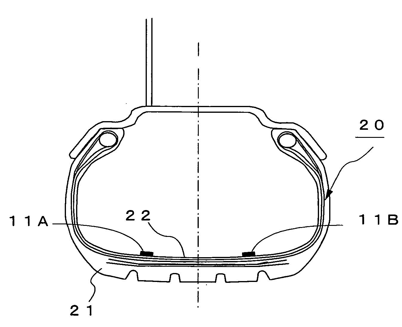
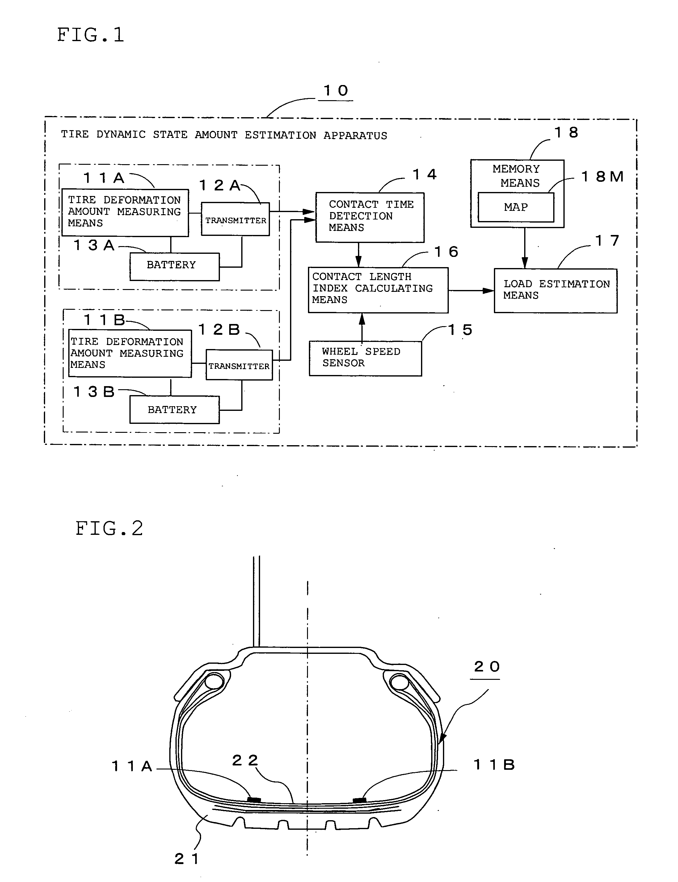
[0145]FIG. 1 is a functional block diagram showing the constitution of a tire dynamic state amount estimation apparatus 10 according to Embodiment 1 of the present invention, and FIG. 2 is a diagram of a tire 20 with sensors according to the present invention. In these figures, 11A and 11B denote tire deformation amount measuring means for measuring the deformation amount of an inner liner portion 22 which is deformed by an input into a tire tread 21 from the road surface, 12A and 12B transmitters for transmitting the measurement data of the above tire deformation amount measuring means 11A and 11B, 13A and 13B batteries for supplying power to the above tire deformation amount measuring means 11A and 11B and the above transmitters 12A and 12B, 14 contact time detection means for detecting the contact time during which the tire 20 with sensors is in contact with the road surface based on temporal in the deformation amount of the inner liner portion 22 which are the outputs of the abo...

embodiment 2

[0161] In the above Embodiment 1, strain in the circumferential direction at the positions which are axisymmetrical in the axial direction about the center in the axial direction of the tire of the inner liner portion 22, a change in strain in the circumferential direction, or bending strain outside the tread surface is measured to obtain the average value k of contact length indices kA and kB at the above two positions, and a load applied to the tire 20 with sensors is estimated from the average value k of contact length indices. Lateral force generated in the above tire can be estimated from the ratio R of the above contact length indices kA and kB at the above two positions.

[0162] That is, when lateral force is generated in the tire 20 with sensors, as shown in FIGS. 5(a) and 5(b), its contact shape becomes such that the contact length on one side of the center in the axial direction of the tire becomes large and the contact length on the other side becomes small. Then, when the...

embodiment 3

[0187] Lateral force generated in the tire 20 with sensors is estimated from the ratio R of contact length indices and the ratio of the indices of deformation length outside the contact patch in the above Embodiment 2. It is possible to estimate longitudinal force generated in the above tire from the ratio Z of the indices of deformation length before and after the contact patch as will be described hereinafter.

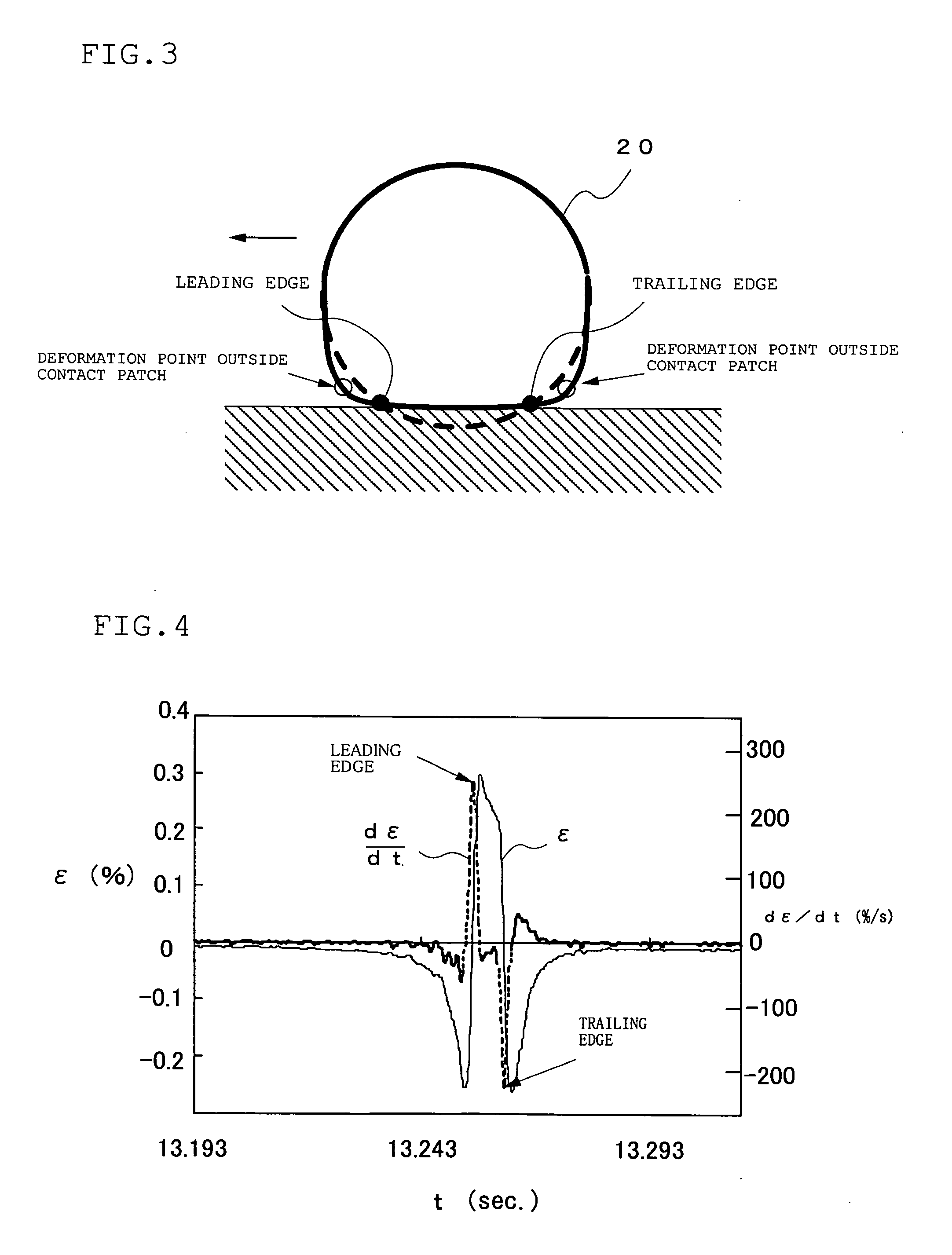
[0188] The ratio Z of the indices of deformation length before and after the contact patch is obtained by calculating the lengths between the deformation points outside the contact patch shown by the white circles in FIG. 3 and the contact ends shown by the black circles on the front side of the contact patch (tread side) and the rear side of the contact patch (kick side). Since longitudinal force and the ratio of the indices of deformation length before and after the contact patch show a very good relationship as will be described hereinafter, a map showing the relationship...


PUM


Abstract

The dynamic state amount of a tire when a load is applied to the tire while running can be estimated accurately and stably by installing tire deformation amount measuring means 11A and 11B at axisymmetrical positions which are equally distant in the axial direction from the center in the axial direction of the tire on the cross-section in the radial direction of the tire on the inner side of the belt portion of a tire tread in the radial direction, such as at the inner surface of the tread, between an inner liner and a ply, between plies or between a ply and a belt to measure the waveforms of deformation of the tire, detecting the contact time which is the time difference between contact edges from the waveforms of deformation, calculating contact length indices kA and kB
from the contact time and the wheel speed detected by a wheel speed sensor 15, calculating the average value k of the above indices kA and kB, and obtaining a load applied to the tire by using the calculated average value k of the indices of contact length and a map 18M showing the relationship between the average value of the indices of contact length and load pre-stored in memory means 18.

Description

BACKGROUND OF THE INVENTION [0001] 1. Field of the Invention [0002] The present invention relates to a method and apparatus for estimating the dynamic state amount of a tire when a load or lateral force is applied to the tire and a tire with sensors at the inner liner portion of a tire tread for measuring the amount of deformation of the tire while running. [0003] 2. Description of the Prior Art [0004] To enhance the running stability of an automobile, it is desired that force (tire generation force) generated in the tire such as a load, lateral force or longitudinal force should be estimated accurately and fed back to the control system of the automobile. It is considered that higher level of control of an ABS brake or a body attitude controller making use of this would become possible with this information, thereby further improving safety. [0005] As means of estimating force generated in a tire by using the tire like a sensor in the prior art, there is proposed a method in which ...

Claims


Application Information

Patent Timeline
IPC IPC(8): G01M17/02G01L5/00B60C19/00B60C23/00B60C23/06B60C23/20G01L5/20
CPCB60C23/0411B60C19/00B60C23/064B60C2019/004
Inventor MORINAGA, HIROSHIWAKAO, YASUMICHIKOBAYAKAWA, AKIRA
Owner BRIDGESTONE CORP
Why Eureka
Try Eureka