System for Delivery of a Tracer in Fluid Transport Systems and Use Thereof

a fluid transport system and system technology, applied in the field of system for delivery of tracer in, can solve the problems of difficult to know from which well or zone in the well the fluid is produced, difficult to position or install more conventional mechanical injection equipment, and limited available and accessible volume of the delivery system

Inactive Publication Date: 2007-10-18
RESMAN AS
View PDF13 Cites 29 Cited by
  • Summary
  • Abstract
  • Description
  • Claims
  • Application Information

AI Technical Summary

Benefits of technology

[0006] The present application proposes a specific tracer delivery system that has been tested. The claimed system is composed of melamine formaldehyde resin (MFR) doped with various tracer materials. The MFR is used to slowly release tracer compounds into a liquid system. The MFR/tracer mixture is applied as part of a monitoring system where tracer is delivered from the MFR/tracer mixt...

Problems solved by technology

In several types of well operation there is a need for tracer delivery systems, which are able to release tracers at places where it will, due to practical constrains, be difficult to position or install more conventional mechanical injection equipment.
Due to the complexity of m...

Method used


Image

  • System for Delivery of a Tracer in Fluid Transport Systems and Use Thereof
  • System for Delivery of a Tracer in Fluid Transport Systems and Use Thereof
  • System for Delivery of a Tracer in Fluid Transport Systems and Use Thereof

Examples


example 1

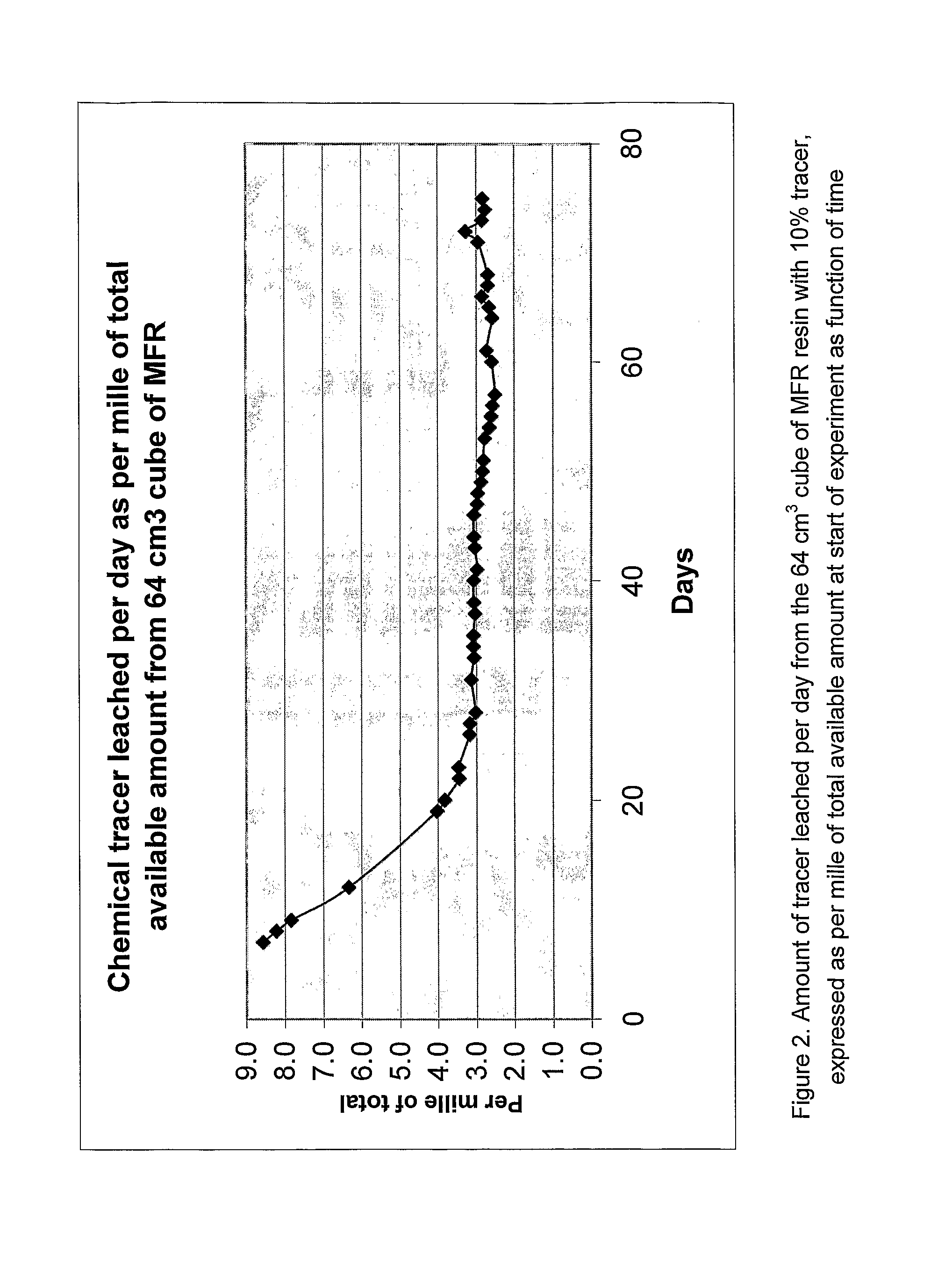
[0022] In the example reported here a MFR cube with a side length of 4 cm has been prepared containing 10% by weight of chemical tracer compound. This experiment has been carried out at a temperature of 90° C. The MFR in this experiment was made from Dynomel M-765.

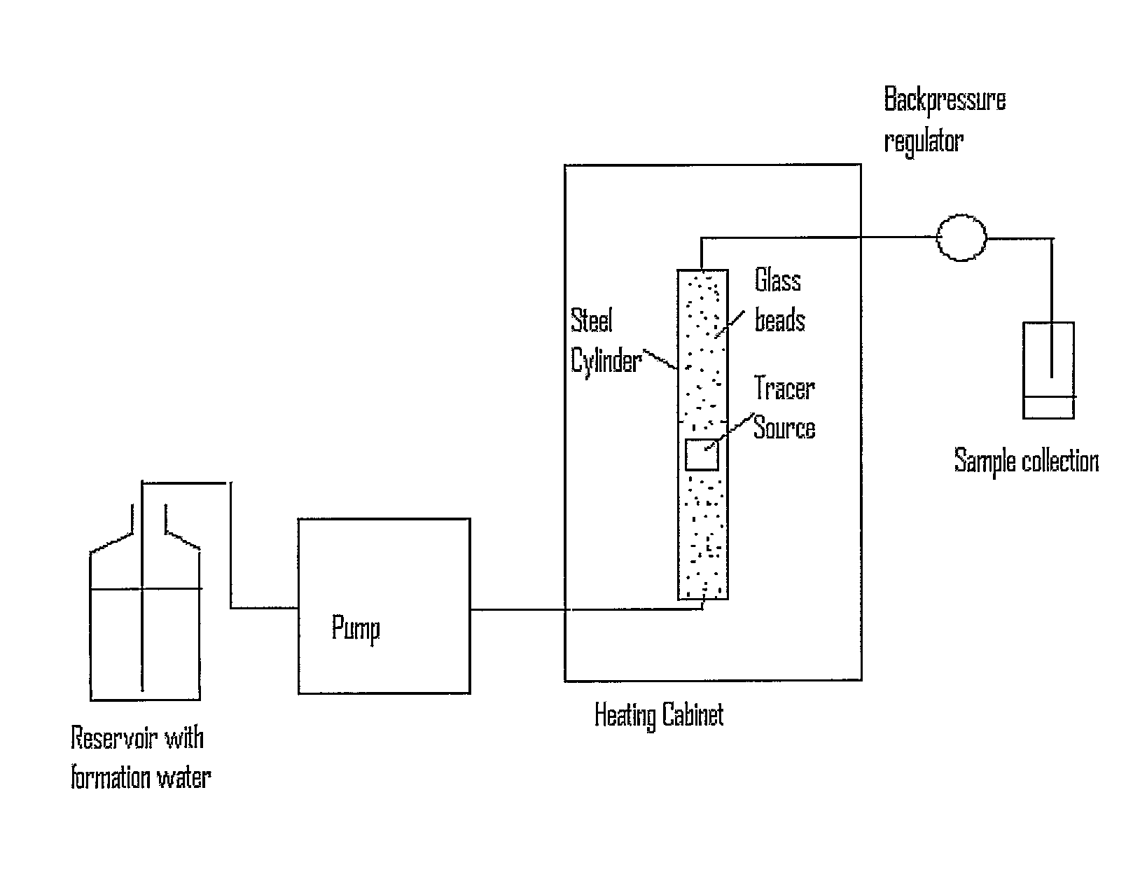
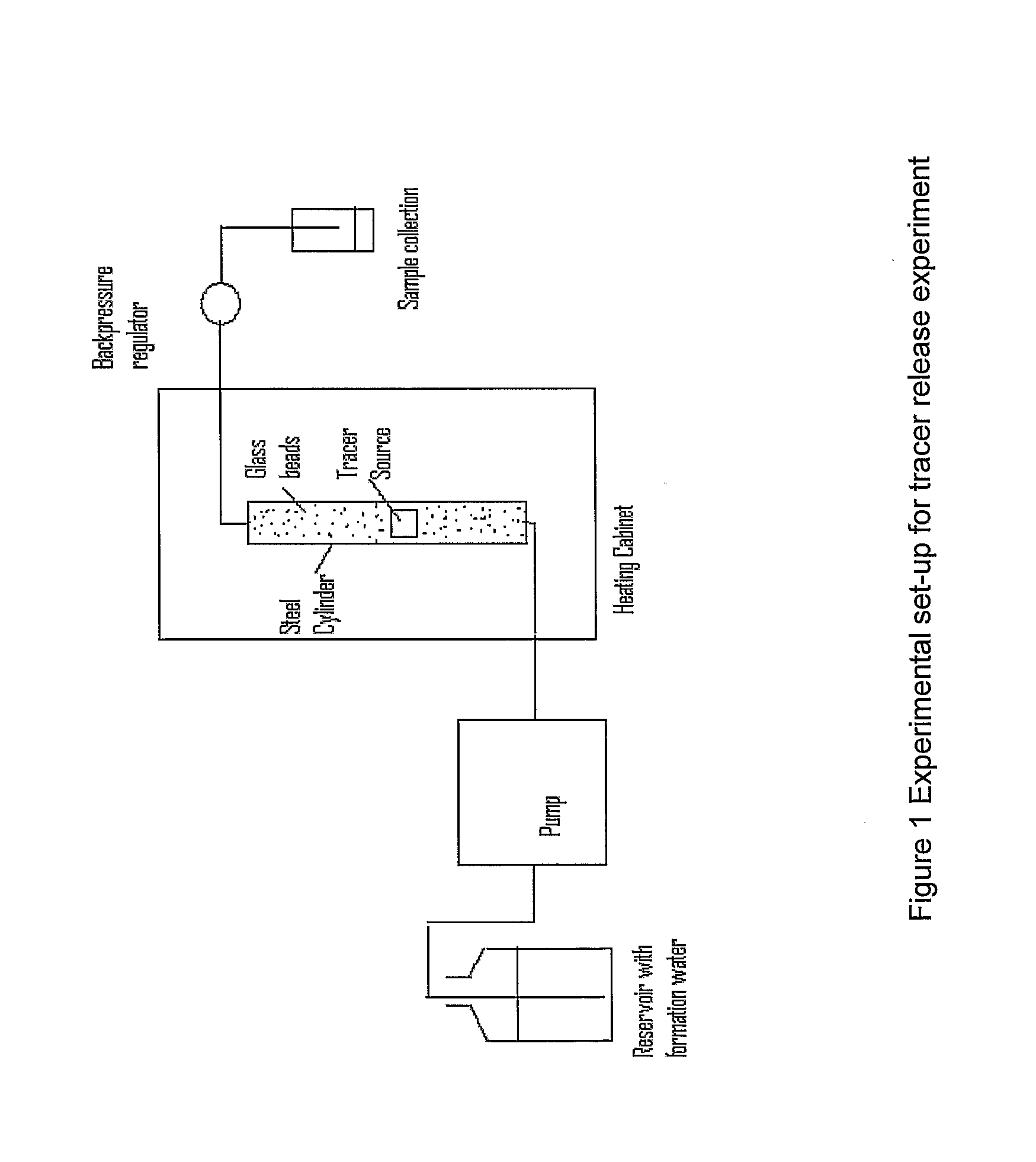
[0023] The cube was placed in a pressure container as shown in FIG. 1. In the example saline water, comparable to what can be expected in an oil reservoir, has been used as the flowing phase. The system allows testing at different temperatures, pressure and flow rates. FIG. 2 provides an example of the measured release rates. The release rate measured was about 0.3% / day of the total tracer amount in the actual cube. The release rate will depend upon the geometry and accessible surface of the MFR system. The obtained release rate shows that the polymer can last for about one year releasing tracer at rates suitable for detection downstream using state-of-the-art analytical methods.

example 2

[0024] The set-up for Example 2 is shown in FIG. 3.

[0025] A hole of 3 mm diameter was drilled through a cube of MFR made from Dynomel M-765 with size 20×20×7 mm containing 10% chemical tracer. One length of stainless steel tubing was inserted into the hole from each side of the cube so that only a length of 5 mm of the hole in the resin was exposed to the formation water that was flowing through. The tracer source was placed in a heating oven at 90° C. and the flow rate of formation water was set at 0.5 ml per minute. The measured release rate is shown in FIG. 4.

[0026] Both examples show that it is possible to construct tracer sources from MFR doped with chemical tracer that will provide a fairly constant release of tracer over time.


PUM


Abstract

The present application proposes a specific tracer delivery system that has been tested. The claimed system is composed of melamine formaldehyde resin (MFR) doped with various tracer materials. The MFR is used to slowly release tracer compounds into a liquid system. The MFR/tracer mixture is applied as part of a monitoring system where tracer is delivered from the MFR/tracer mixture at a specific location up-stream and detected at some location downstream, thereby verifying fluid flow from that specific location up-stream. The MFR can be doped with different types of tracers, thereby allowing placement of different tracers at several different positions upstream. Production from the various labelled zones can be verified through the analysis of one sample downstream.

Description

FIELD OF THE INVENTION [0001] The present invention relates to a specific tracer delivery system composed of a melamine formaldehyde resin (MFR) doped with various tracer materials. The MFR / tracer mixture is used as part of a monitoring system where tracer is delivered from the MFR / tracer mixture at a specific location upstream and detected at some location downstream, thereby verifying fluid flow from that specific location upstream. The system is intended for long-term monitoring of fluid inflow in production wells in oil reservoirs. BACKGROUND OF THE INVENTION [0002] Tracers are used to follow fluid flow in various systems such as oil reservoirs, process flow lines, ground water is leakage studies etc. Tracers are released up-stream and detected downstream. Analysing tracer concentration downstream may give information about flow rates, dilution volumes, communication, fluid mixing, mass residence time distribution etc. Tracers may be injected into the system by a variety of meth...

Claims


Application Information

Patent Timeline
IPC IPC(8): G01T1/16E21BE21B47/10
CPCE21B47/1015C09K8/03E21B47/11
Inventor STRAY, HELGEDUGSTAD, OYVINDHASSFJELL, SINDRE
Owner RESMAN AS
Why Eureka
Try Eureka