Fuse Module

a fuse module and fuse technology, applied in the field of fuse modules, can solve the problems of structural complexity, affecting the operation of the fuse module, and the application of the fuse member is liable to be limited to a region with extremely low possibility of meltdown, and achieves the effect of simple structur

Inactive Publication Date: 2007-10-18
AUTONETWORKS TECH LTD +2
View PDF16 Cites 11 Cited by
  • Summary
  • Abstract
  • Description
  • Claims
  • Application Information

AI Technical Summary

Benefits of technology

[0022] This circuit assembly enables a power distribution from a common power supply to a plurality of the power input sections through the fuse elements, in a simple structure where the fuse module is simply attached to the circuit assembly.
[0023] In the fuse module-equipped circuit assembly, the circuit assembly may include a current-detection bus bar with an input terminal and an output terminal between which a detection-target current is allowed to flow, at least one of the input terminal and output terminals held in the insulation housing. The incorporation of the current-detection bus bar in the circuit assembly add a current-detection function to the circuit assembly, while at least one of the input

Problems solved by technology

In the aforementioned structure where the fuse element is attached to each of the tab terminals perpendicularly bent from the bus bar board in place, the fuse elements are scattered on the bus bar board, which is liable to cause structural complexity, and difficulty in concentrated management of the fuse ele

Method used


Image

  • Fuse Module
  • Fuse Module
  • Fuse Module

Examples


Embodiment Construction

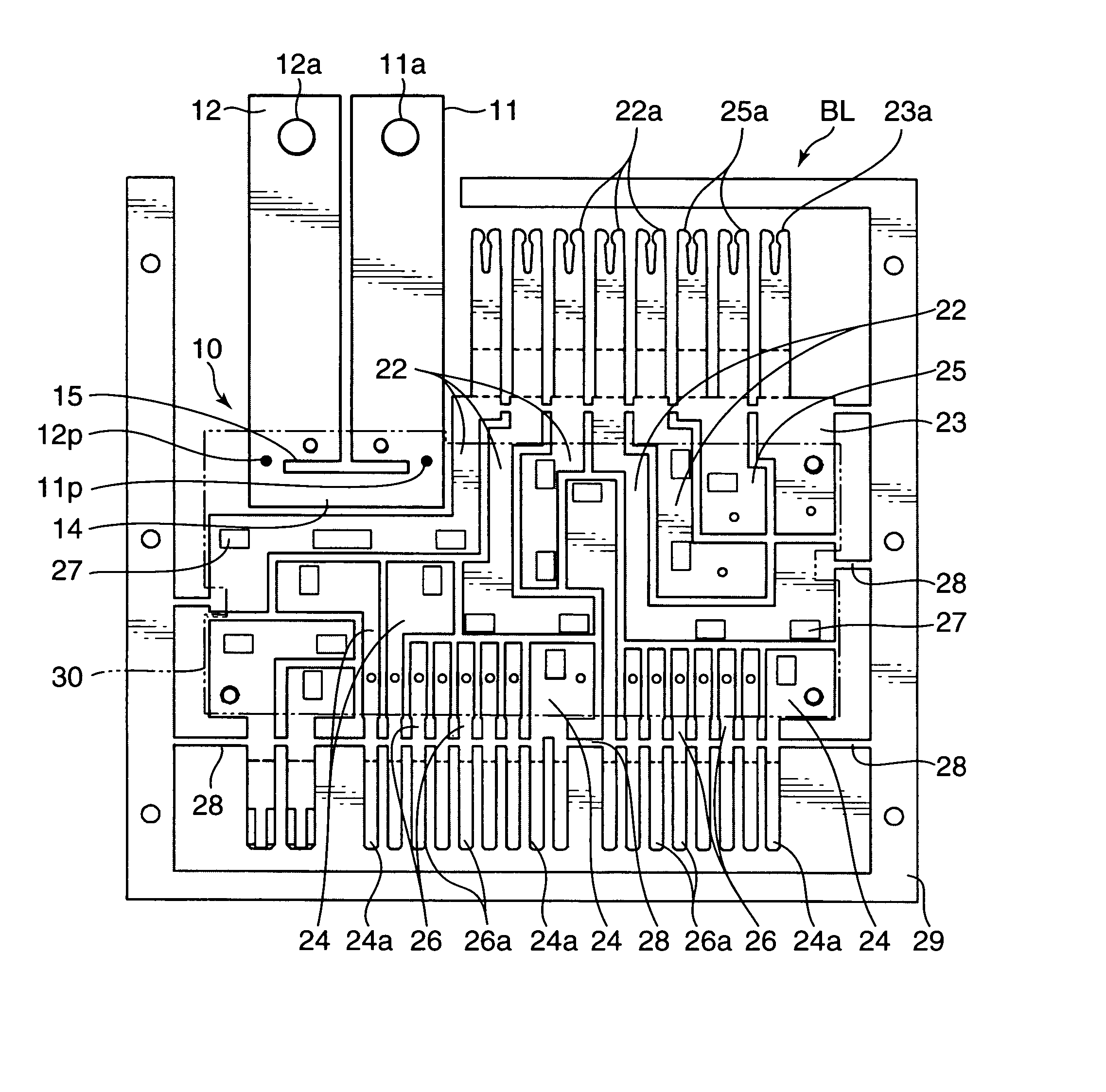
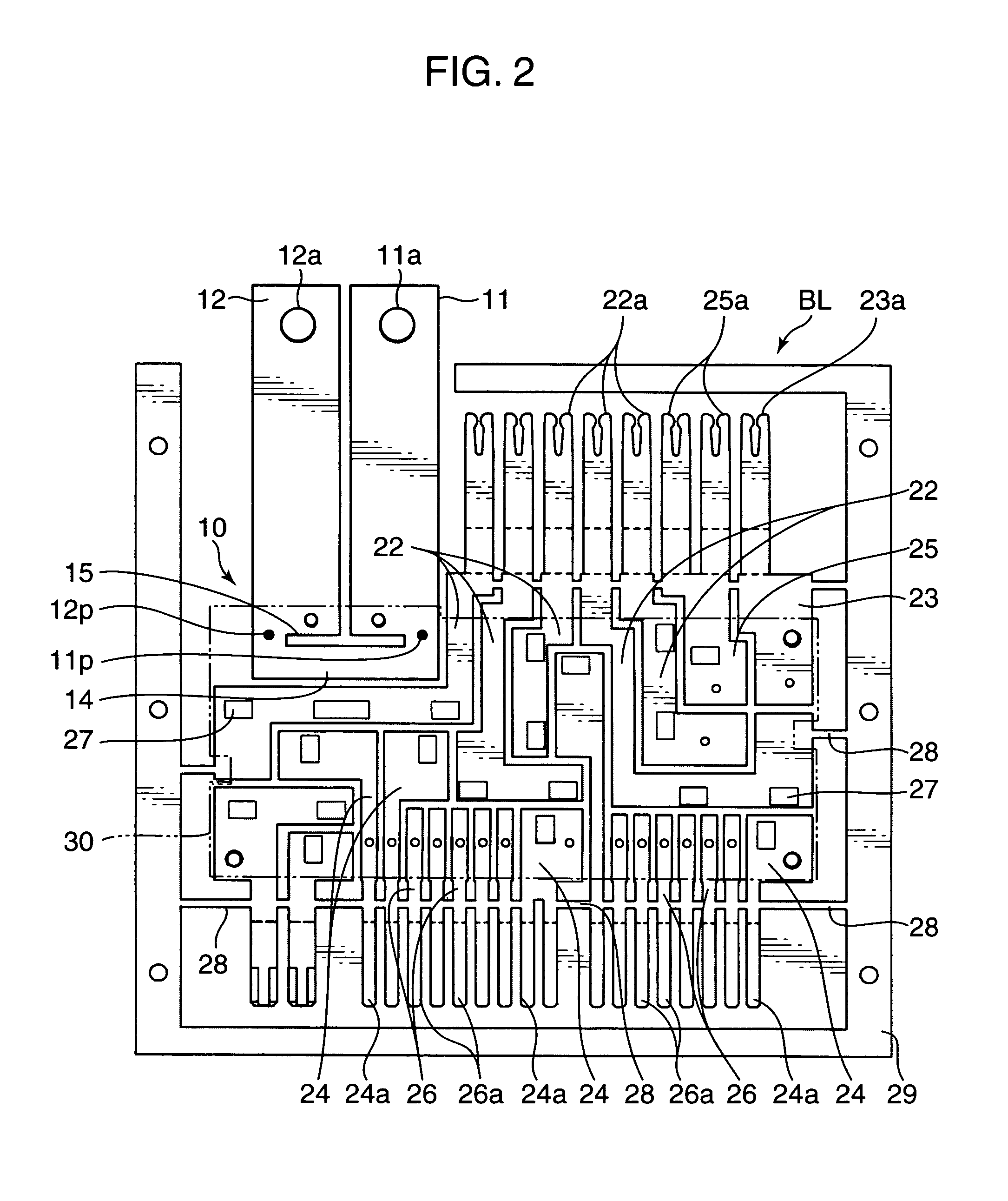
[0041] A preferred embodiment of the present invention will be described based on the drawings. In this embodiment, there is attached a fuse module 50 illustrated in FIG. 7 to a circuit assembly with an array of bus bars illustrated in FIGS. 2 to 4 to construct a power distributor illustrated in FIGS. 5 and 6.

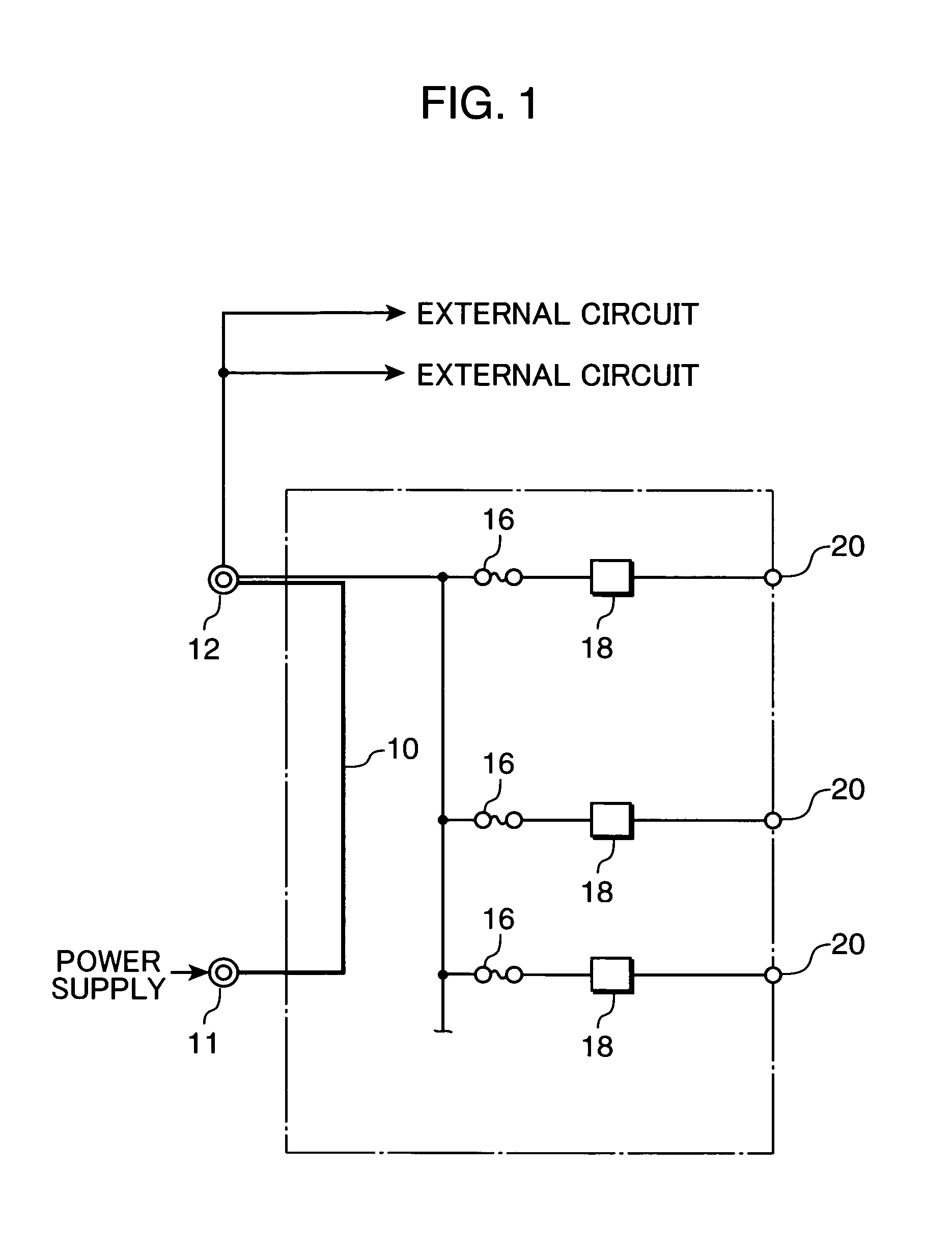
[0042]FIG. 1 is a circuit diagram showing the configuration of a major portion of a power circuit formed in the circuit assembly. This circuit assembly includes a current-detection bus bar 10 constituting a current sensor which will be described in detail later. The current-detection bus bar 10 has an input terminal 11 to be connected to an unillustrated vehicle-mounted power supply (that is alternator in this embodiment), and an output terminal 12. The output terminal 12 of the current-detection bus bar 10 has a branching connection to a plurality of output terminals 20, and a fuse element 16 and a switching element 18 are interposed between the output terminal 12 and each of...


PUM


Abstract

It is an object to provide a fuse module having a power distribution function of distributing a common power to a plurality of power input sections and a function of protecting a circuit from an overcurrent during the power distribution based on fuse elements interposed in the circuit, while allowing for replacement and concentrated management of the fuse elements. A fuse module as specific means for achieving the object is adapted to connect a common power supply to a plurality of power-input sections of a circuit assembly, and provided with an insulation housing 52, a branch-connection conductor 54 and a plurality of power-input conductors which are held in the insulation housing. The branch-connection conductor 54 has an input terminal 55 adapted to be connected to the power supply, and a plurality of fuse-connection terminals 54a disposed correspondingly to the respective power-input sections. Each of the power-input conductors is electrically connected to a corresponding one of the power-input sections, and has a fuse-connection terminal and disposed in a pair with a corresponding one of the fuse-connection terminals 54a. Then, a fuse element is installed in each of a plurality of fuse-installation portions arranged in the insulation housing 52 so as to be connected to the fuse-connection terminal 54a of the branch-connection conductor 54 and the corresponding fuse-connection terminal of the power-input conductor to be interposed between the fuse-connection terminals of the pair.

Description

TECHNICAL FIELD [0001] The present invention relates to a fuse module to be interposed between a power supply and a circuit assembly mounted on an automobile or the like. BACKGROUND ART [0002] Heretofore, as a circuit assembly for distributing a power from a common power supply to a plurality of loads in a vehicle such as an automobile, there has been generally known an electric connection box including a bus bar board. The bus bar board is of a laminated construction with alternating bus bar layers serving as a power circuit and insulating plates. From each of the bus bar layers are perpendicularly bent a plurality of tab terminals, to which circuit-protective fuse elements and switching elements such as a relay switch are connected. [0003] Late years, there has also been known a power distributor intended to reduce a thickness of the circuit assembly, as disclosed in the following Patent Publication 1. In this power distributor, a switching element consisting of a FET or the like ...

Claims


Application Information

Patent Timeline
IPC IPC(8): H01H85/04H01H85/20B60R16/02H01H85/50H05K7/02
CPCH01H85/2035H05K7/026H01H2085/208
Inventor BESSHO, TERUTAKASASAKI, YOSHIKAZUBABASAKI, TOMOHIROKANOU, TOMOKI
Owner AUTONETWORKS TECH LTD
Why Eureka
Try Eureka