
Contactless electron joystick of universal joint structure using single hall sensor

Inactive Publication Date: 2007-10-18
DONG A UNIV RES FOUND FOR IND ACAD COOP
View PDF7 Cites 17 Cited by
  • Summary
  • Abstract
  • Description
  • Claims
  • Application Information

AI Technical Summary

Benefits of technology

[0008]It is another object of the present invention to provide a contactless electron joystick of a universal joint structure using a single hall sensor in which a bar shaped permanent magnet engaged at a lower side of a joystick bar helps forming a horizontal vector with respect to an axial direction magnetic flux of a bar magnet on a two-dimension plane of a hall sensor in sync with an operation of a universal joint, and the hall sensor detects a horizontal vector for thereby controlling a direction and speed of a control object such as a motored wheel chair.
[0009]It is further another object of the present invention to provide contactless electron joystick of a universal joint structure using a single hall sensor in which a human body engineering design-based easier use is obtained with the use of a universal joint structure, and it is easy to diagnose failures with its simple structure, and an assembling process is simple, and work efficiency may be maximized, and an enhanced vibration resistance structure is obtained.

Problems solved by technology

However, a nonlinear operation is performed in a two-dimension motion between a hall sensor output signal and an end of a joystick bar.
In addition, in the above two hall sensor structures, since a permanent magnet is provided at each rotary shaft for measuring rotation angles, a design dimension increases, and an apparatus design may be more complicated due to a vibration resistance design.
However, in the above structure, the rotation assembly needs a huge volume in the whole installation areas of the apparatus.
A magnetic force line of a permanent magnet may have a certain eccentric formation, while deviating from a center of a hall sensor plane due to an abrasion of rotary shaft after a long time use, so that accuracy may be disadvantageously affected.
Since the above deviation may be variable based on a user or a use environment, a real time compensation cannot be performed.

Method used


Image

  • Contactless electron joystick of universal joint  structure using single hall sensor
  • Contactless electron joystick of universal joint  structure using single hall sensor
  • Contactless electron joystick of universal joint  structure using single hall sensor

Examples


embodiment

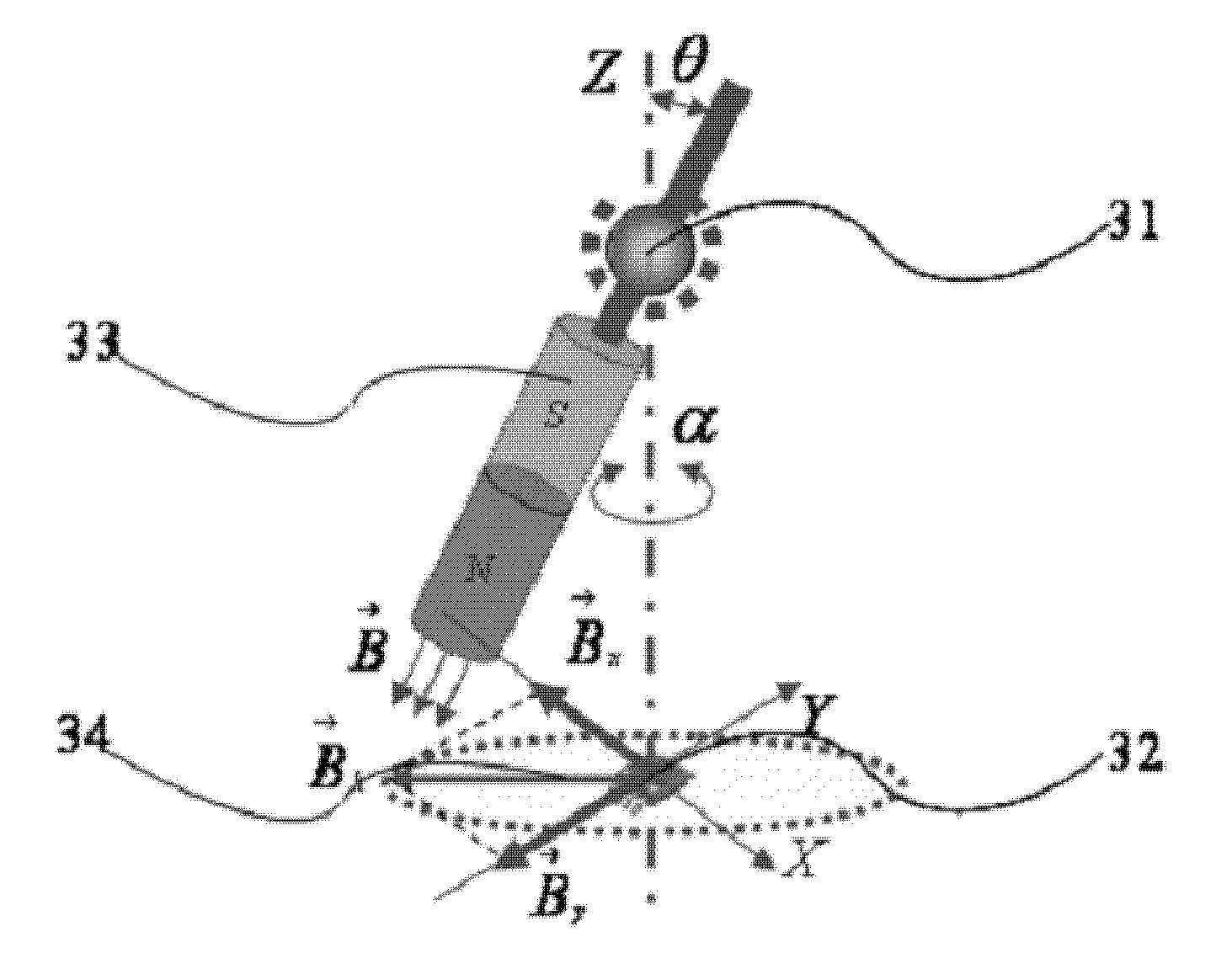
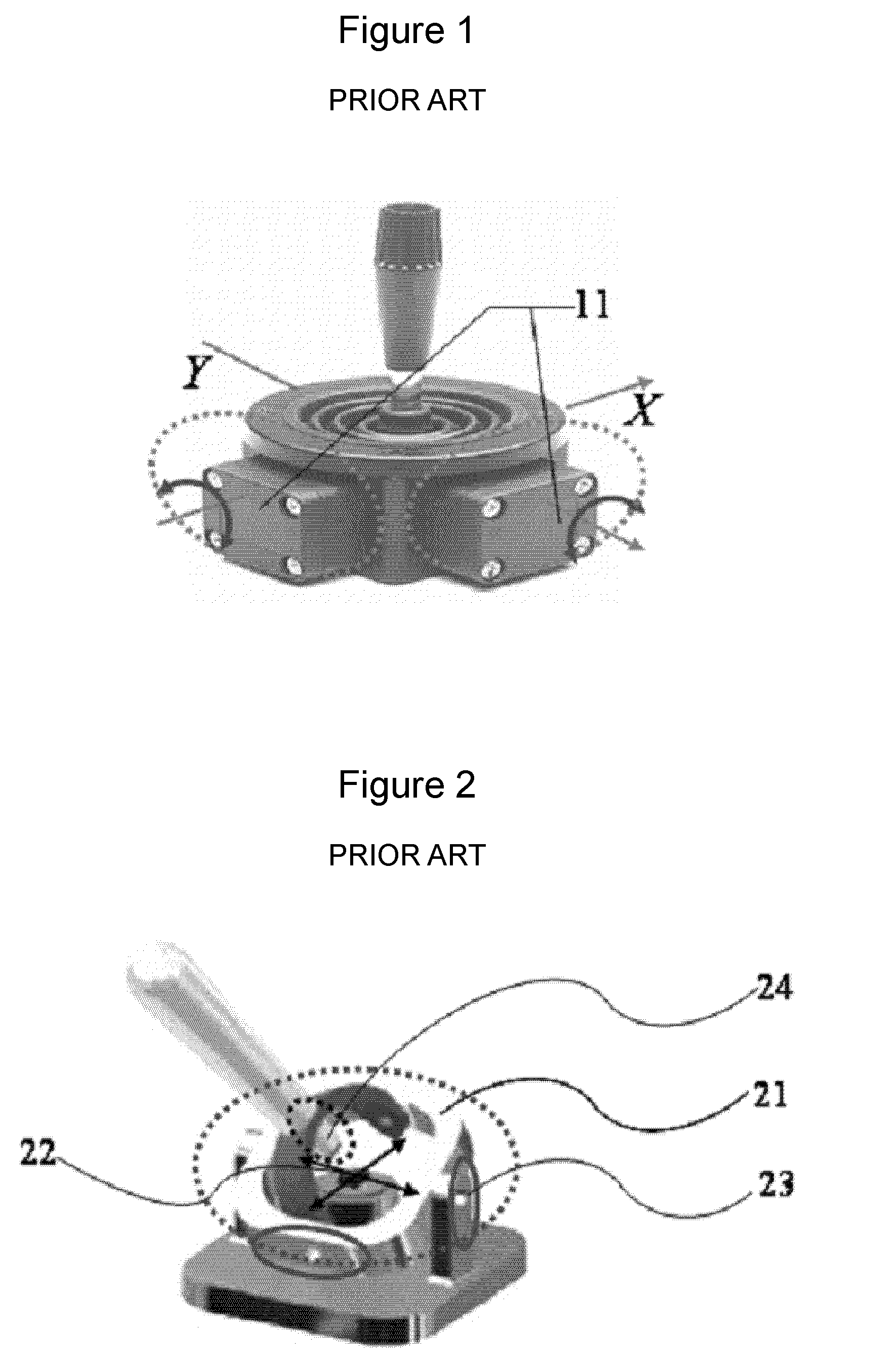
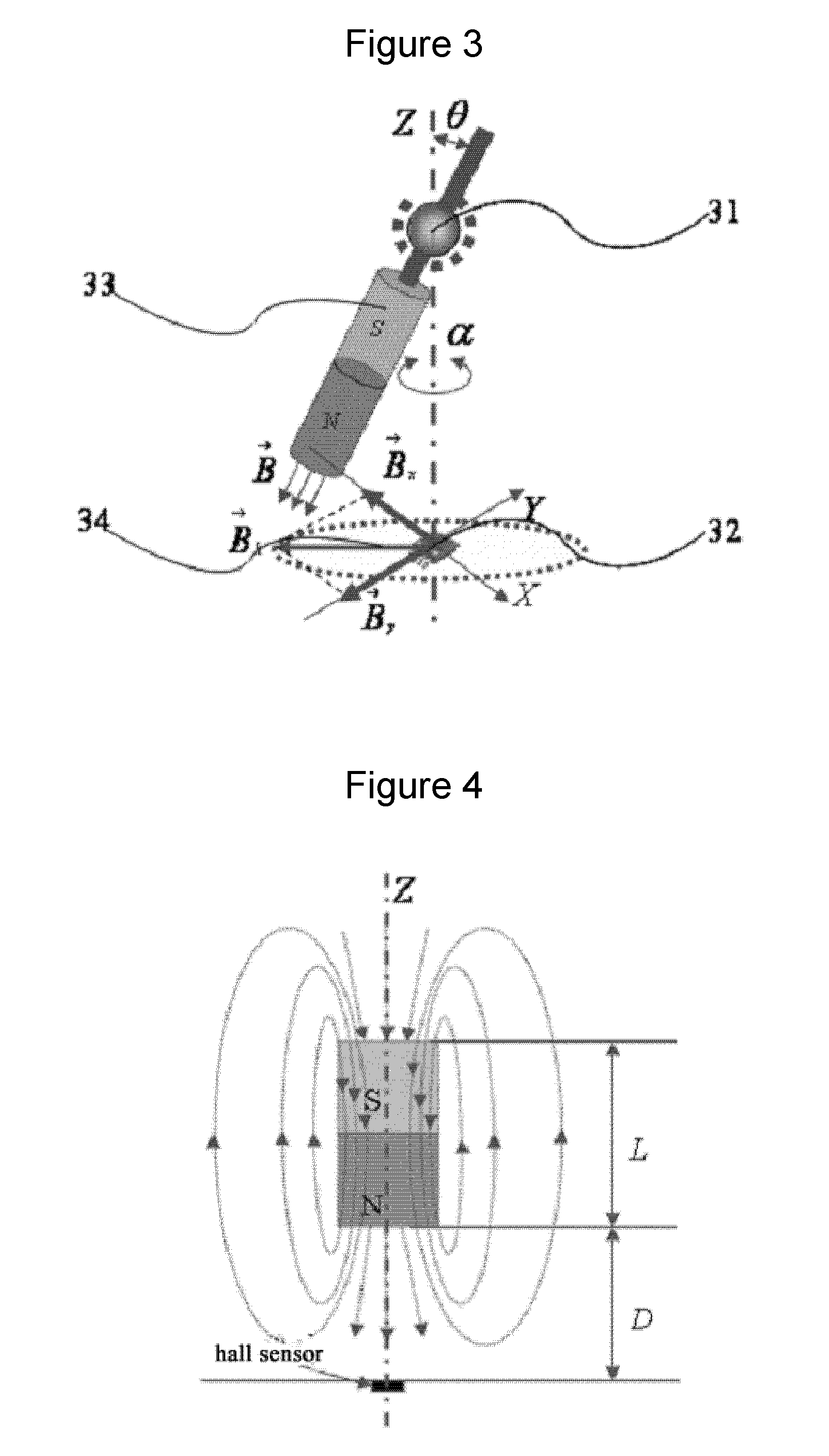
[0041]FIG. 3 is a view illustrating a construction of a contactless electron joystick of a universal joint structure using a single hall sensor according to the present invention.

[0042]In the present invention as compared to the conventional joystick structure of FIG. 1, the magnetic force lines of the permanent magnet are oriented toward the rotation center of the universal joint 31. When the permanent magnet is inclined at θ by the motion of the universal joint 31, the magnetic response intensity {right arrow over (B)} of the center line helps forming a horizontal vector {right arrow over (Bh)} 34 on the plane of the hall sensor 32, and the horizontal components Bx, By are detected at the center of the plane of the hall sensor 32. Here, the hone sensor 32 outputs a signal having a phase of 90° corresponding to two components. Bx, By may be expressed as follows.

Bh=λ(θ)B sin(θ)  [Formula 1]

[0043]where λ(θ) represents a function which represents a nonlinear effect formed based on the...


PUM


Abstract

A contactless joystick of a universal joint structure using a single hall sensor is disclosed, in which a two-dimension coordinate of an end of a joystick bar is obtained based on a principle that a rotation of a horizontal vector of a magnetic field is detected using a hall sensor, and a human body engineering design can be obtained with a universal joint structure, and it is easy to diagnose a certain failure with its simple structure, and a simple assembly is obtained, and work efficiency can be maximized, and an enhanced vibration resistance structure is obtained.

Description

TECHNICAL FIELD[0001]The present invention relates to a contactless joystick of a universal joint structure using a single hall sensor, and in particular to a contactless joystick of a universal joint structure using a single hall sensor in which a two-dimension coordinate of an end of a joystick bar is obtained based on a principle that a rotation of a horizontal vector of a magnetic field is detected using a hall sensor, and a human body engineering design can be obtained with a universal joint structure, and it is easy to diagnose a certain failure with its simple structure, and a simple assembly is obtained, and work efficiency can be maximized, and an enhanced vibration resistance structure is obtained.BACKGROUND ART[0002]FIG. 1 is a perspective view illustrating a conventional electron joystick structure having two sensor structures.[0003]As shown therein, in a conventional contactless electron joystick, a hall sensor is engaged at rotation axes x and y of a joystick bar, and ...

Claims


Application Information

Patent Timeline
IPC IPC(8): G09G5/08A61G5/04G01B7/00G05G1/00
CPCG05G9/047G05G2009/04755G05G2009/04707G06F3/02G06F3/00
Inventor YANG, JAE WOOLEE, JANG MYUNGLEE, HYO MOONCHOI, JOON YOUNGJIN, HONG ZHE
Owner DONG A UNIV RES FOUND FOR IND ACAD COOP
Learn More