DC converters

a converter and converter technology, applied in the field of dc converters, can solve the problems of reducing the service life of the converter, unable to facilitate the so-called soft or resonant switching of the switch, and the disadvantage of such dc converters

Inactive Publication Date: 2007-10-18
POWER INTEGRATIONS INC
View PDF4 Cites 54 Cited by
  • Summary
  • Abstract
  • Description
  • Claims
  • Application Information

AI Technical Summary

Benefits of technology

[0016] Preferably the flyback or forward converter output circuit includes a diode or a further switch coupled between a junction of the primary winding with the switch of the converter output circuit and another of the input terminals for limiting voltage stress on the switch of the converter output circuit.

Problems solved by technology

While such DC converters can be advantageous for the reduced voltage stresses that they provide for the MOSFET switches, they do not facilitate providing so-called soft or resonant switching of the switches.
Consequently, switching losses remain a disadvantage of such DC converters.

Method used


Image

  • DC converters
  • DC converters
  • DC converters

Examples


Embodiment Construction

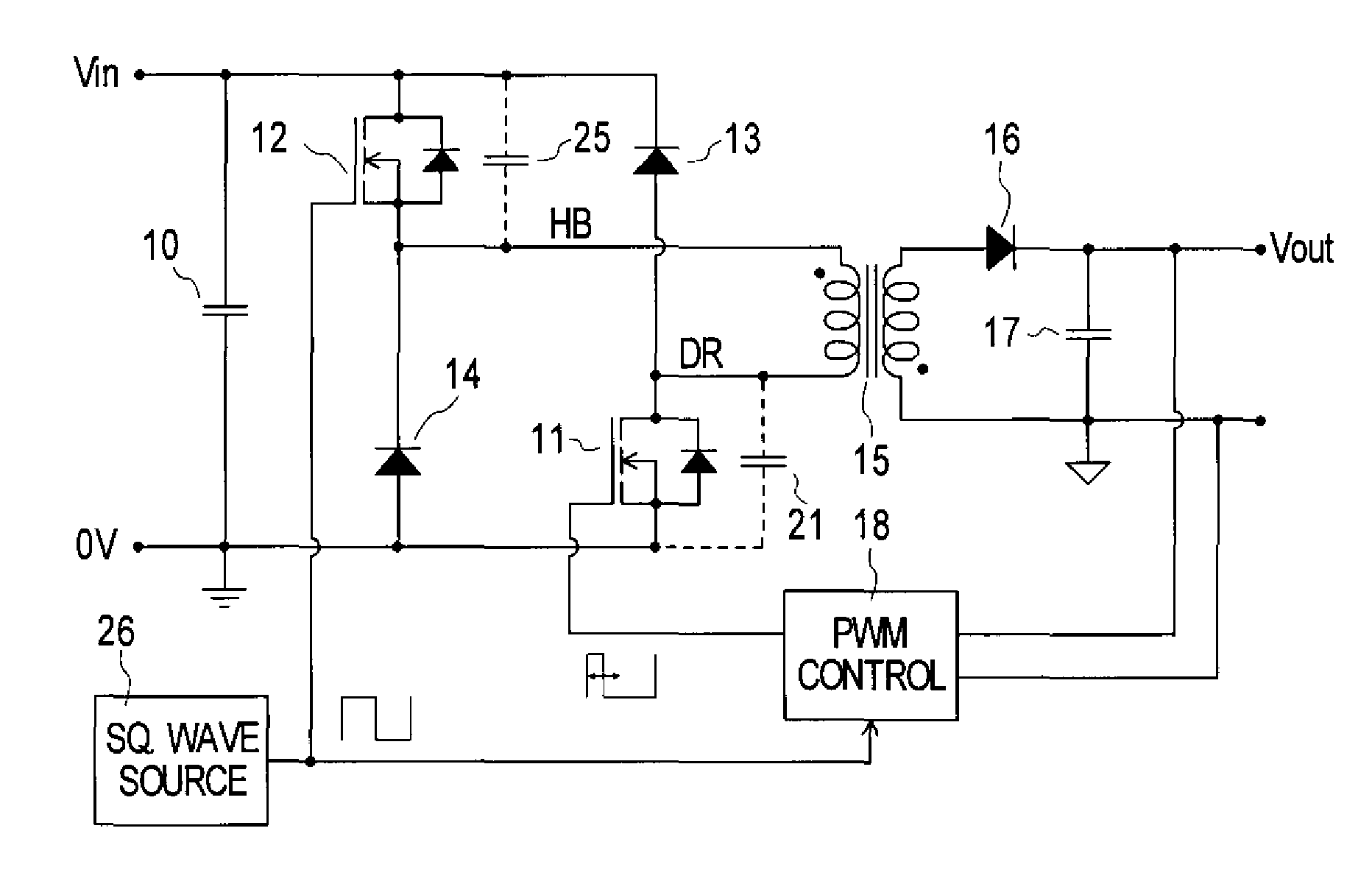
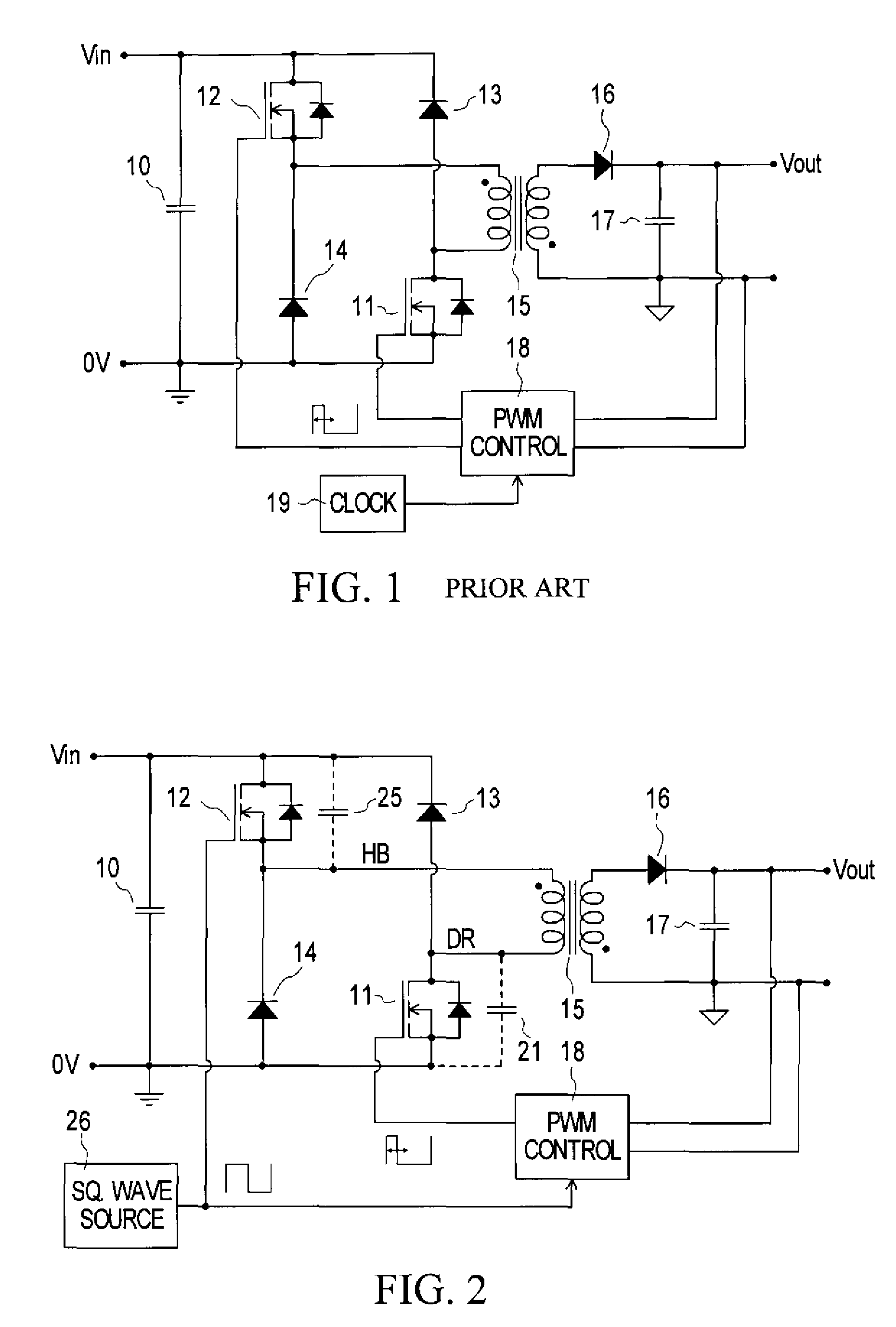
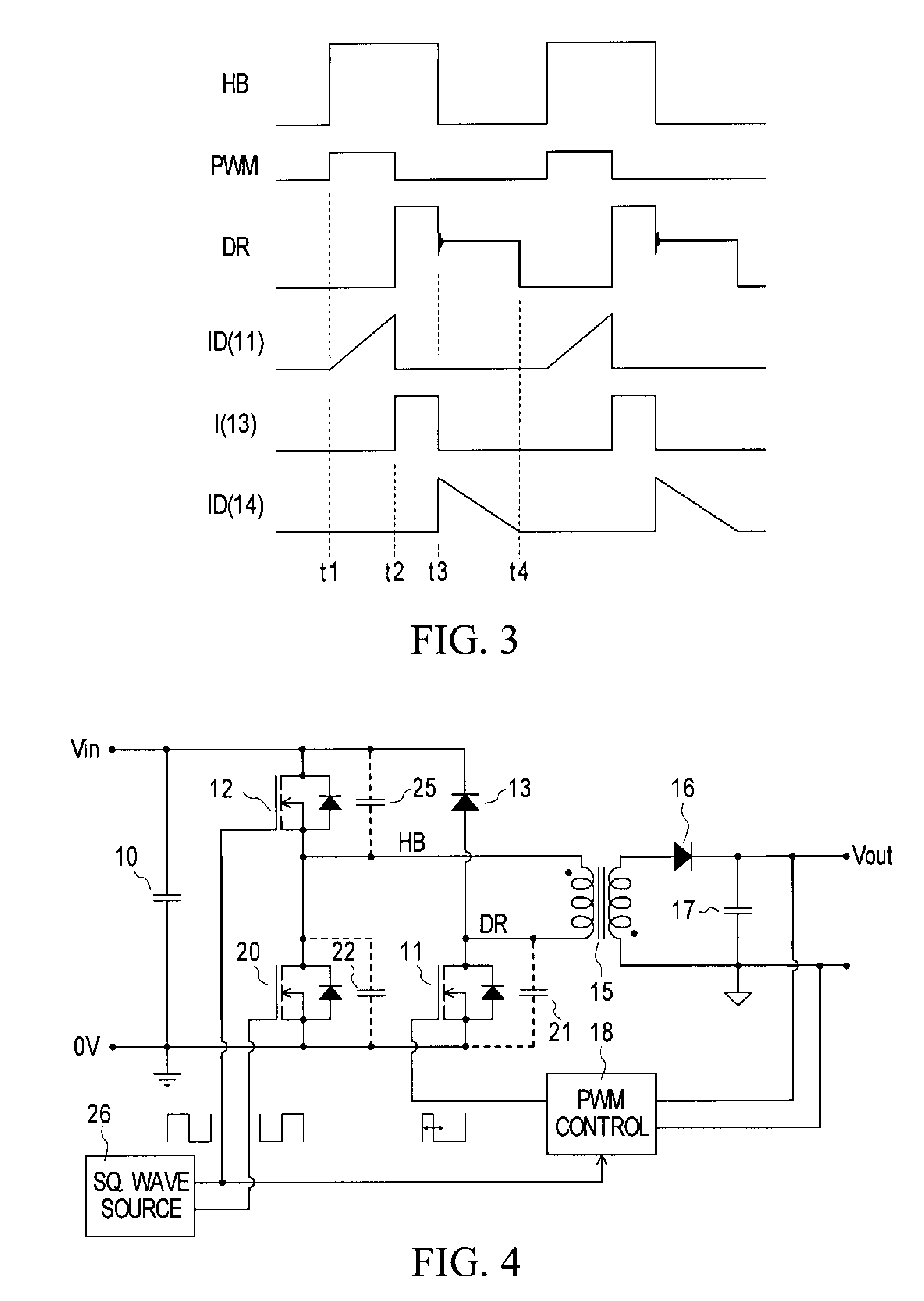
[0030]FIG. 1 schematically illustrates a known form of flyback converter having a half-bridge or two-transistor primary switching arrangement. A forward converter can have a similar primary switching arrangement, differing in its configuration on the secondary side of the transformer, as is well known.

[0031] In the flyback converter of FIG. 1, an input voltage source Vin, relative to a zero voltage 0V or ground reference, smoothed by an input capacitor 10, is switched by a half-bridge primary switching arrangement of two MOSFETs 11, 12 and two diodes 13, 14 to a primary winding of a flyback transformer 15, a secondary winding of which is coupled via a diode 16 to an output capacitor 17 to produce an output voltage Vout. Dots adjacent the transformer windings indicate the winding senses or polarities in conventional manner. A PWM (pulse width modulation) control unit 18, supplied with a clock signal at a desired switching frequency of the converter from a clock source 19, is supplie...


PUM


Abstract

A DC converter comprises a half bridge supply circuit and one or more flyback or forward converter output circuits, and optionally also an LLC converter whose control can determine a common variable switching frequency. The half bridge supply circuit produces a 50% duty output alternating between two input voltages, such as zero and a voltage Vin. In each flyback or forward converter output circuit, a switch connects a transformer primary to the half bridge supply circuit output in a PWM controlled manner to regulate a respective flyback or forward converter DC output which is produced by the converter output circuit, with a duty ratio less than 50% whereby switching losses are reduced. Soft switching is further facilitated by the half bridge supply circuit having two transistors controlled in a complementary manner.

Description

[0001] This application claims the benefit of U.S. Provisional Application No. 60 / 788,719 filed Apr. 4, 2006, the entire contents and disclosure of which are hereby incorporated herein by reference.[0002] This invention relates to DC converters, which are also referred to by other names such as DC-DC converters; DC or DC-to-DC regulators; switch mode regulators, converters, power converters, or power supplies; and so on. The term “DC converter” or simply “converter” is used herein to include all such terms. BACKGROUND [0003] DC converters can have various configurations or forms, including so-called flyback and forward converters. In order to reduce voltage stresses on MOSFET switches in such DC converters, it is known to provide a forward converter or a flyback converter with a half-bridge or two-transistor primary switching arrangement. Flyback and forward converters can have similar such primary switching arrangements, so that they may differ from one another only on the secondar...

Claims


Application Information

Patent Timeline
Patent Type & Authority Applications(United States)
IPC IPC(8): H02M3/335
CPCH02M3/335
Inventor ORR, RAYMOND K.
Owner POWER INTEGRATIONS INC
Why Eureka
Try Eureka