Torque converter bypass clutch control

a torque converter and clutch technology, applied in the direction of gearing control, gearing elements, gearing, etc., can solve the problems of low operating efficiency of torque converters, low control and strategy, and low efficiency of bypass clutches, so as to improve city drive schedule fuel economy

Inactive Publication Date: 2007-10-18
FORD GLOBAL TECH LLC
View PDF13 Cites 35 Cited by
  • Summary
  • Abstract
  • Description
  • Claims
  • Application Information

AI Technical Summary

Benefits of technology

[0010] The method improves city drive schedule fuel economy.

Problems solved by technology

Because of slippage between the input and output, the torque converter has a low operating efficiency.
However, the bypass clutch, damper, control and strategy are usually not optimized to produce maximum fuel economy under city driving conditions.

Method used


Image

  • Torque converter bypass clutch control
  • Torque converter bypass clutch control
  • Torque converter bypass clutch control

Examples


Embodiment Construction

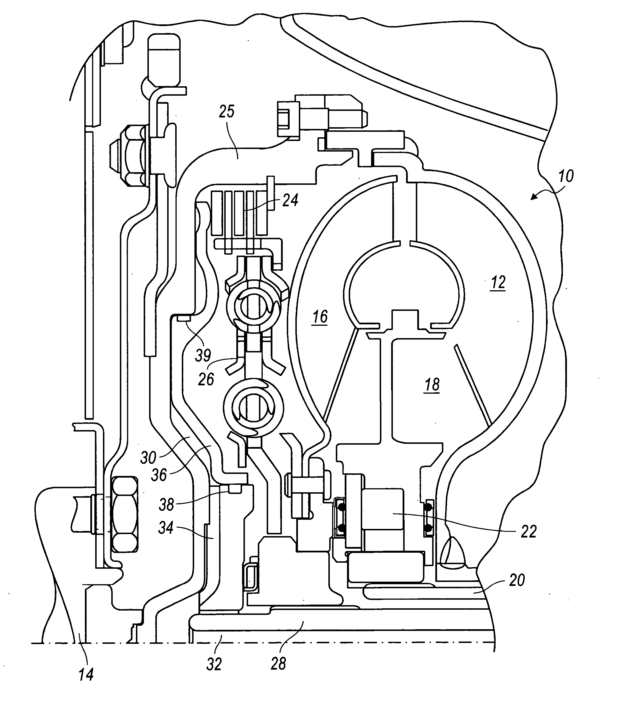
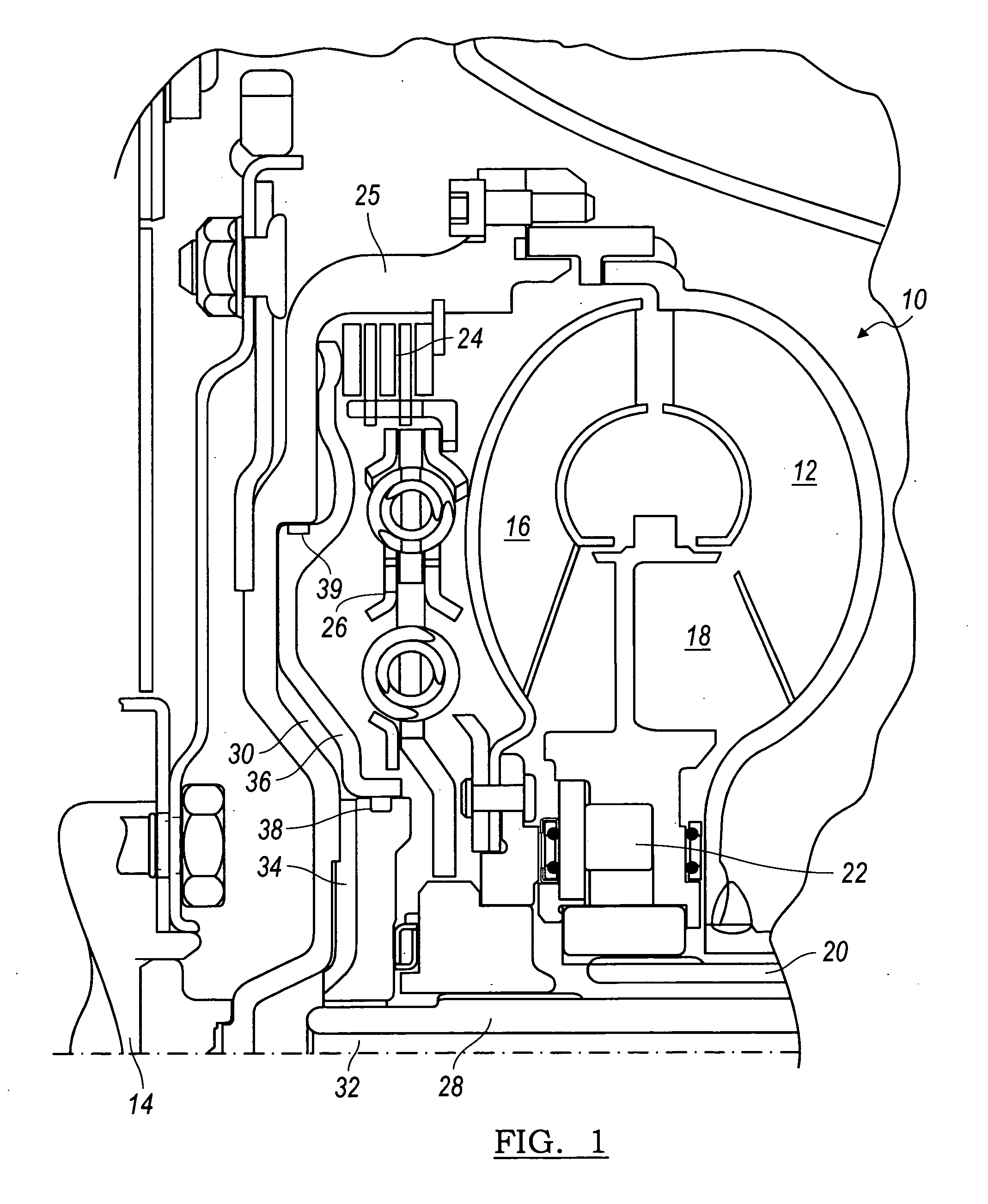
[0018] Referring first to FIG. 1, a torque converter 10 includes a bladed impeller wheel 12 connected to the crankshaft 14 of an internal combustion engine, a bladed turbine wheel 16, and a bladed stator wheel 18. The impeller, stator and turbine wheels define a toroidal fluid flow circuit, whereby the impeller is hydrokinetically connected to the turbine. The stator 18 is supported rotatably on a stationary stator sleeve shaft 20, and an overrunning brake 22 anchors the stator to shaft 20, thereby preventing rotation of the stator in a direction opposite the direction of rotation of the impeller, although free-wheeling motion in the opposite direction is permitted.

[0019] The torque converter assembly 10 includes a bypass clutch 24 located within the torque converter housing 25. The torque output side of lockup clutch 24 includes a damper 26, located between the impeller and a turbine shaft, which is the transmission input shaft 28. The damper 26 may incorporate dual or single-stag...


PUM


Abstract

A method of using a torque converter bypass clutch to launch a vehicle, mitigate transient vibration, and mitigate vehicle natural frequency harshness. The method uses the torque converter when the bypass clutch power capacity is approaching its limit, when the vehicle load is high, or the vehicle is on a grade, where normally the bypass clutch would launch the vehicle.

Description

BACKGROUND OF THE INVENTION [0001] The present invention relates generally to controlling the bypass clutch of a torque converter for an automotive vehicle. [0002] A conventional automatic transmission includes a torque converter, located in the power path between an engine crankshaft and transmission input shaft. A torque converter includes a bladed impeller wheel driveably connected to the engine crankshaft, a bladed turbine wheel driveably connected to the transmission input shaft, a bladed stator wheel, and a toroidal chamber containing pressurized hydraulic fluid for producing a hydrokinetic connection between the impeller and turbine. The torque converter attenuates torque transients and vibrations, increases torque transmitted to the turbine from the impeller at low speed, and provides a smooth transition during gear ratio changes. Because of slippage between the input and output, the torque converter has a low operating efficiency. [0003] Current automotive automatic transmi...

Claims


Application Information

Patent Timeline
Patent Type & Authority Applications(United States)
IPC IPC(8): B60W10/00
CPCF16H61/143Y10T477/638F16H2045/0284F16H2312/02F16H2061/145Y10T477/63385Y10T477/6352Y10T477/6403Y10T477/755Y10T477/6418Y10T477/735Y10T477/757Y10T477/78Y10T477/79F16H61/50
Inventor BREVICK, JOHN E.
Owner FORD GLOBAL TECH LLC
Why Eureka
Try Eureka