Calibration method for mixed-mode simulation

a mixed-mode simulation and calibration method technology, applied in the field of mixed-mode simulation, can solve the problems of falling behind the real output signal sreal, the design of analog/mixed signals becomes increasingly complicated, and ordinary simulation tools such as spice and fast spice cannot meet current simulation requirements, so as to achieve the effect of increasing the simulation speed and the circuit area

Inactive Publication Date: 2007-10-18
IND TECH RES INST
View PDF3 Cites 8 Cited by
  • Summary
  • Abstract
  • Description
  • Claims
  • Application Information

AI Technical Summary

Benefits of technology

[0025]Further, circuit area to be simulated can be selected very small, and simulation speed increases accordingly.

Problems solved by technology

As analog / mixed-signal designs become increasingly complicated, ordinary simulation tools such as SPICE and Fast SPICE cannot meet current simulation requirements such as simulation speed and design capacity in system on a chip (SOC).
That is, a problem in conventional mixed-mode simulation is that the digital-to-analog mixed signal SMIXD2A falls behind the realistic output signal SREAL.
Conventional mixed-mode simulation software, CADENCE, SYNOPSYS, or ACADEMIC, all considers only the shape of the transition curve but ignores the problem of the extra delay time ED, resulting in lower simulation accuracy.

Method used


Image

  • Calibration method for mixed-mode simulation
  • Calibration method for mixed-mode simulation
  • Calibration method for mixed-mode simulation

Examples


Embodiment Construction

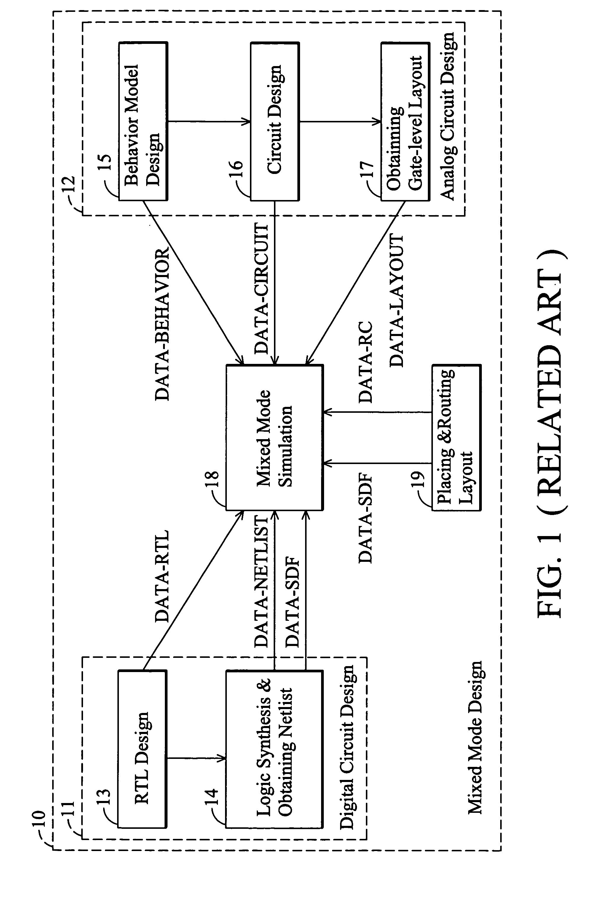
[0040]FIG. 4 is a flowchart of a mixed-signal design provided in the invention, differing from that of FIG. 1 only in that standard delay format DATA-SDF generated in step 14 is not provided directly to a mixed-mode simulator. Rather, it is calibrated to DATA-SDF′ in step 40 before being provided to the mixed-mode simulator. In addition, standard delay format DATA-SDF generated in step 19 can also be calibrated to DATA-SDF′ in step 40 before provided to the mixed-mode simulator.

[0041]The following describes in detail calibration for mixed-mode simulation used in step 40.

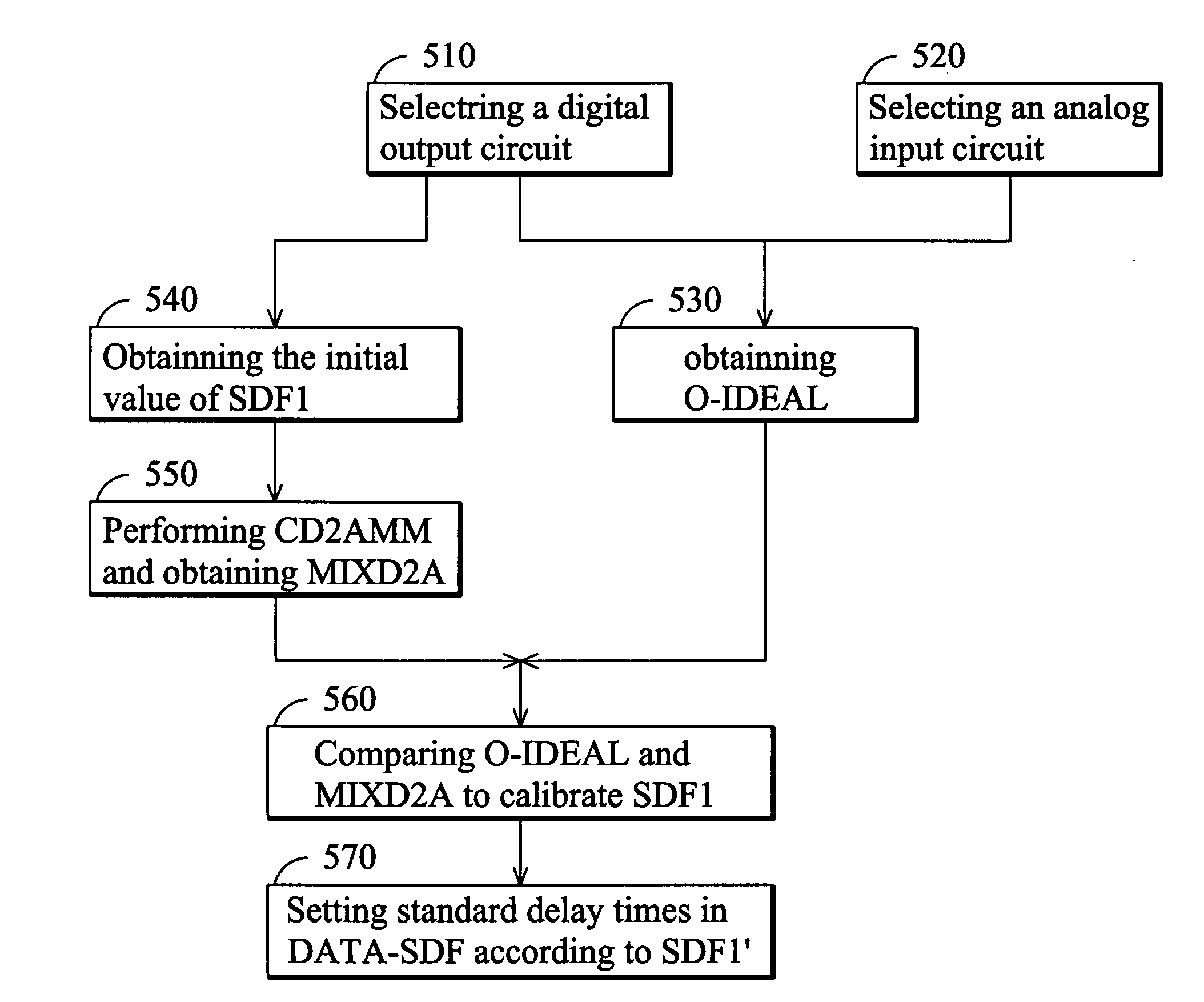
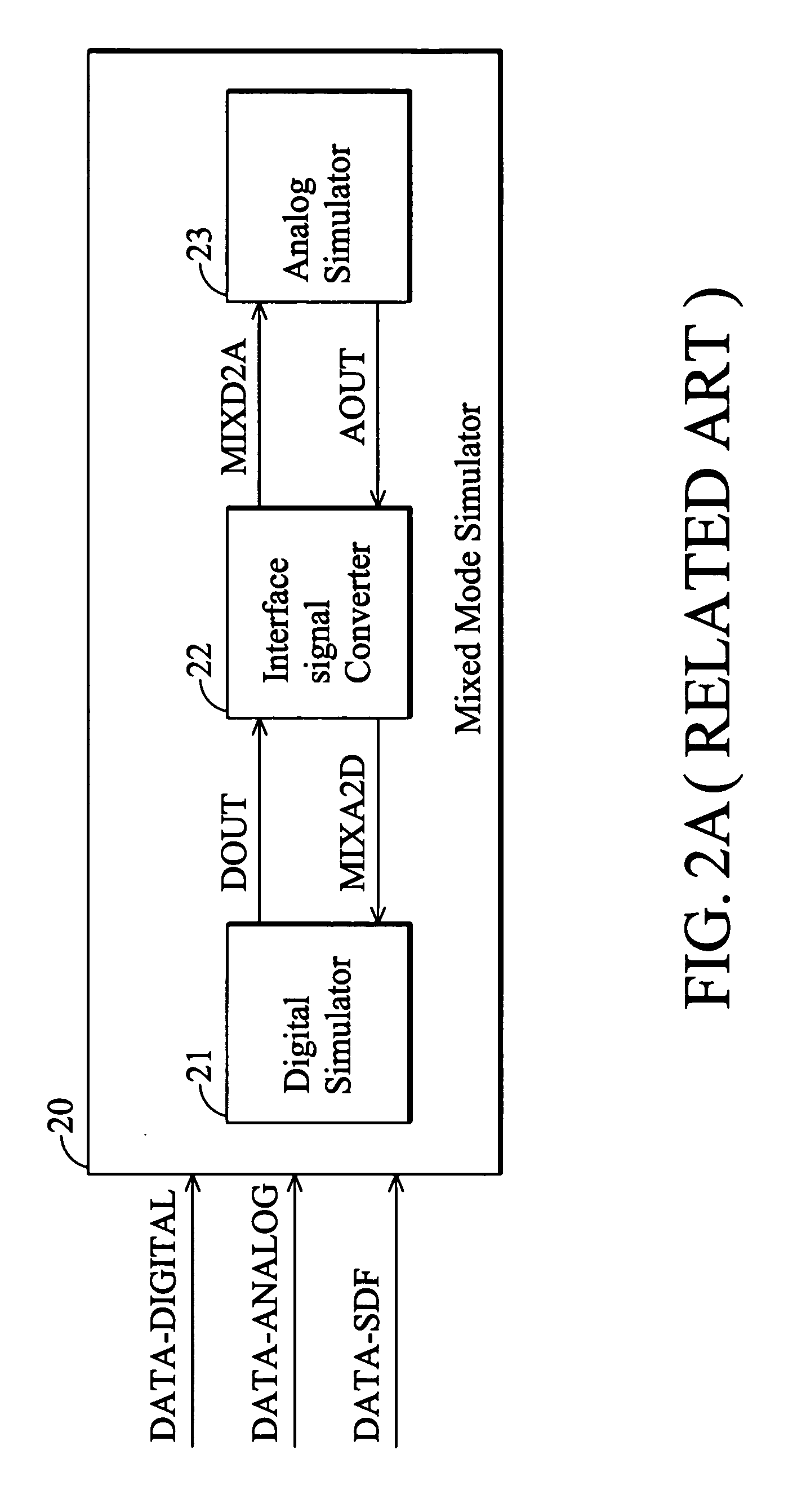
[0042]FIG. 5 is a flowchart of a calibration method for mixed-mode simulation in accordance with an embodiment of the invention. As shown, in step 510, a partial circuit at the output end in a digital circuit on which the mixed-mode simulation is to be performed (digital circuit 24 in FIG. 2) is selected as a digital output circuit. In step 520, a partial circuit at the input end in an analog circuit on which the mix...


PUM


Abstract

A calibration method of a mixed mode simulation calibrates standard delay times in a standard delay format and includes obtaining a digital output circuit from a digital circuit, obtaining an analog output circuit from an analog circuit, performing a simulation on the digital output circuit connected to the analog output circuit to obtain an ideal output, obtaining a first delay time according to the standard delay times of the digital output circuit, performing a calibrative analog-to-digital mixed mode simulation using the first delay time to obtain an analog-to-digital mixed output, comparing the ideal output and the analog-to-digital mixed output to calibrate the first delay time, and calibrating the standard delay times of the digital output circuit according to the calibrated first delay time.

Description

BACKGROUND OF THE INVENTION[0001]1. Field of the Invention[0002]The invention relates to mixed-mode simulation, and in particular to a calibration method for mixed-mode simulation.[0003]2. Description of the Related Art[0004]Integration of analog and digital circuits into a single chip not only enhances overall performance of the chip but also reduces power consumption, chip area, and production costs.[0005]As analog / mixed-signal designs become increasingly complicated, ordinary simulation tools such as SPICE and Fast SPICE cannot meet current simulation requirements such as simulation speed and design capacity in system on a chip (SOC). Electronic Design Automation (EDA) has thus developed a simulation environment for co-operation of digital simulator (such as VERILOG) and analog simulator (such as SPICE), referred to as mixed-mode simulation, for the purpose of solving currently encountered difficulties.[0006]FIG. 1 is a flowchart of a conventional mixed-signal design. The system ...

Claims


Application Information

Patent Timeline
Patent Type & Authority Applications(United States)
IPC IPC(8): G06F17/50
CPCG06F17/5036G06F30/367
Inventor CHANG, YAONG-JARLIN, YUNG-CHIEHHO, JUNG-CHILUO, PEI-WEN
Owner IND TECH RES INST
Why Eureka
Try Eureka