Timer with periodic channel service

Active Publication Date: 2007-10-18
MACOM CONNECTIVITY SOLUTIONS LLC
View PDF3 Cites 2 Cited by
  • Summary
  • Abstract
  • Description
  • Claims
  • Application Information

AI Technical Summary

Benefits of technology

[0010] The present invention timer includes several features that have not been previously available. First, the channels only require one simple register. Conventionally, a master register and a slave register are

Problems solved by technology

First, the channels only require one simple register.

Method used


Image

  • Timer with periodic channel service
  • Timer with periodic channel service
  • Timer with periodic channel service

Examples


Embodiment Construction

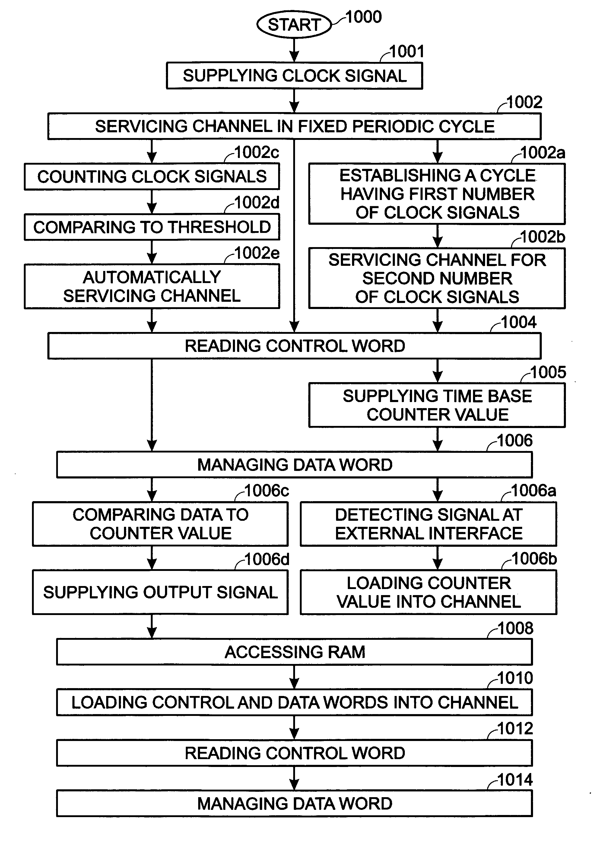
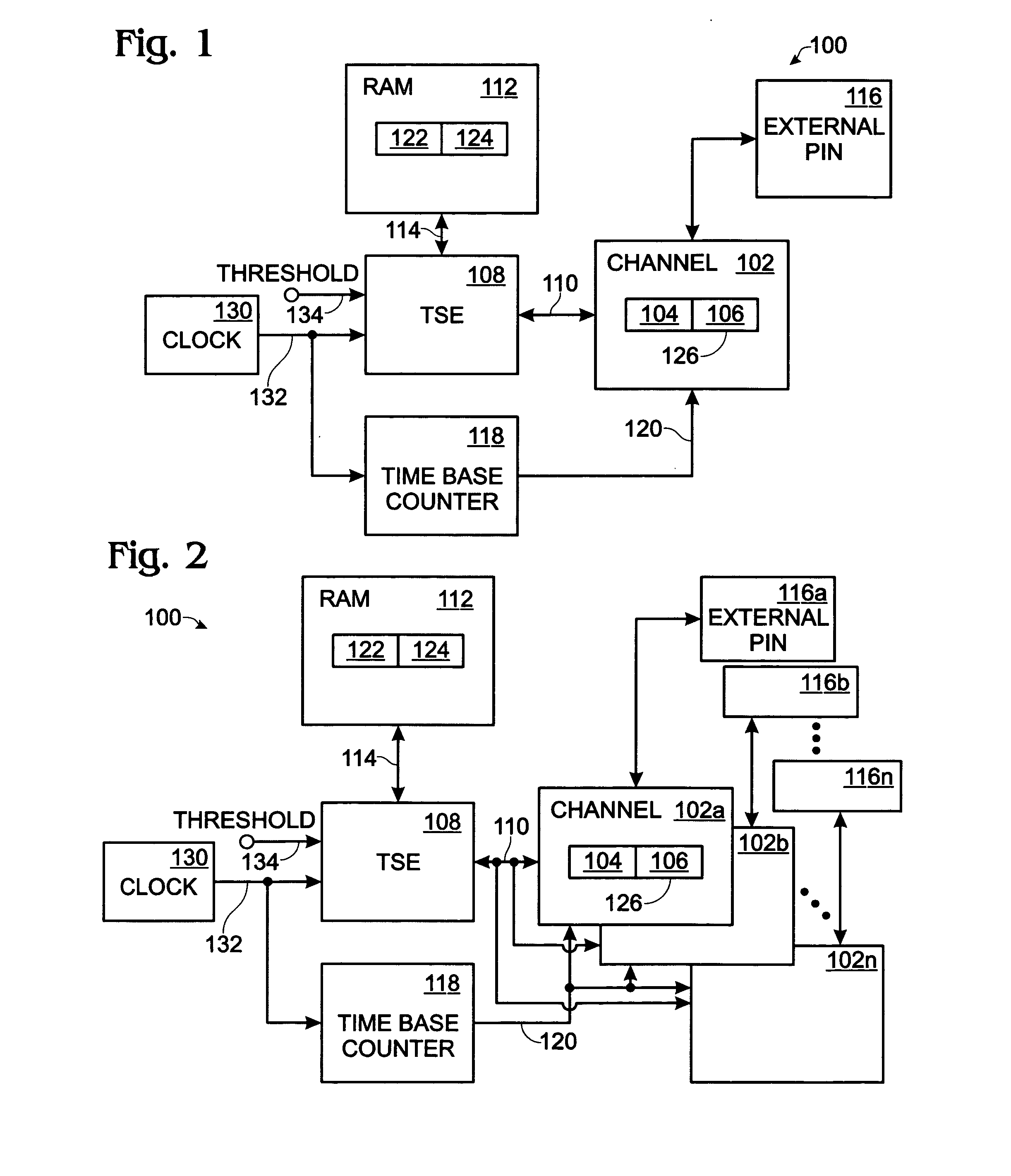
[0026]FIG. 1 is a schematic block diagram of a timer for controlling events with periodic channel service. The timer 100 comprises a channel 102 for monitoring a loaded control word and a loaded data word. The channel 102 reads a first control word 104 to determine an operation, and manages a first data word 106 in response to the determined operation. A timer service engine (TSE) 108 has an interface on line 110 for servicing the channel 102 with control words and corresponding data words in a fixed periodic cycle.

[0027] An internal random access memory (RAM) 112 has an interface connected to the TSE 108 on line 114. For example, in one aspect lines 110 and 114 may be a data / address bus. An external interface pin 116 is connected to the channel 102. As described in more detail below, a pin logic module (not shown) may operate independent of the channel to detect pulse edges and to trigger the channel. For simplicity, the pin logic function is assumed to be part of the channel 102....


PUM


Abstract

A system and method are provided for periodically servicing a channel in a timer used for controlling events. The method services a channel in a fixed periodic cycle, and reads a first control word loaded in the channel to determine a timer operation. Then, a first data word in the channel is managed in response to the determined operation. In one aspect, a clock signal is supplied with a fixed period. Then, servicing the channel in a fixed periodic cycle includes: establishing a cycle having a first number of clock signals; and, servicing the channel for a second number of clock signals each cycle. If the timer includes a plurality of channels, then each channel is serially serviced in a single cycle.

Description

BACKGROUND OF THE INVENTION [0001] 1. Field of the Invention [0002] This invention generally relates to an electrical programmable event timer and, more particularly, to a timer capable of servicing timer channels with a fixed interval periodicity. [0003] 2. Description of the Related Art [0004] Programmable timers are widely used in the data processing and machine control fields. Some of the common tasks performed by most timers include input capture and output compare. An input capture function records (“captures”) the time at which an external event (electrical signal) occurs. For example, input capture may be used to read a limit switch or a temperature. An output compare function generates an output signal in response to programmed time intervals. For example, output compare can be used to run an electrical motor or solenoid. Input capture and output compare functions can be modified in response to commands from an associated programmable logic controller (PLC), programmable co...

Claims


Application Information

Patent Timeline
IPC IPC(8): G06F1/00
CPCG06F1/14
Inventor WILKIE, BRIAN F.WILES, MICHAEL F.QUIRK, JAY DAVID
Owner MACOM CONNECTIVITY SOLUTIONS LLC
Why Eureka
Try Eureka