Internal steam engine

Inactive Publication Date: 2007-10-25
FLATER ANDERS HARALD
View PDF4 Cites 5 Cited by
  • Summary
  • Abstract
  • Description
  • Claims
  • Application Information

AI Technical Summary

Benefits of technology

[0003] In summary, the internal steam engine injects a non-combustible liquid inside the mechanical structure and operational characteristics of the common diesel engine. In contrast to the diesel process, the steam power stroke is accomplished at lower operational temperature and without emission of noxious gases. In comparison with conventional steam engines, which gener

Problems solved by technology

The sheer quantity of oil being burnt for this purpose represent a growing threat to our environment by emission of carbon dioxide which, greenhouse gas, allegedly is the main

Method used


Image

  • Internal steam engine
  • Internal steam engine
  • Internal steam engine

Examples


Example

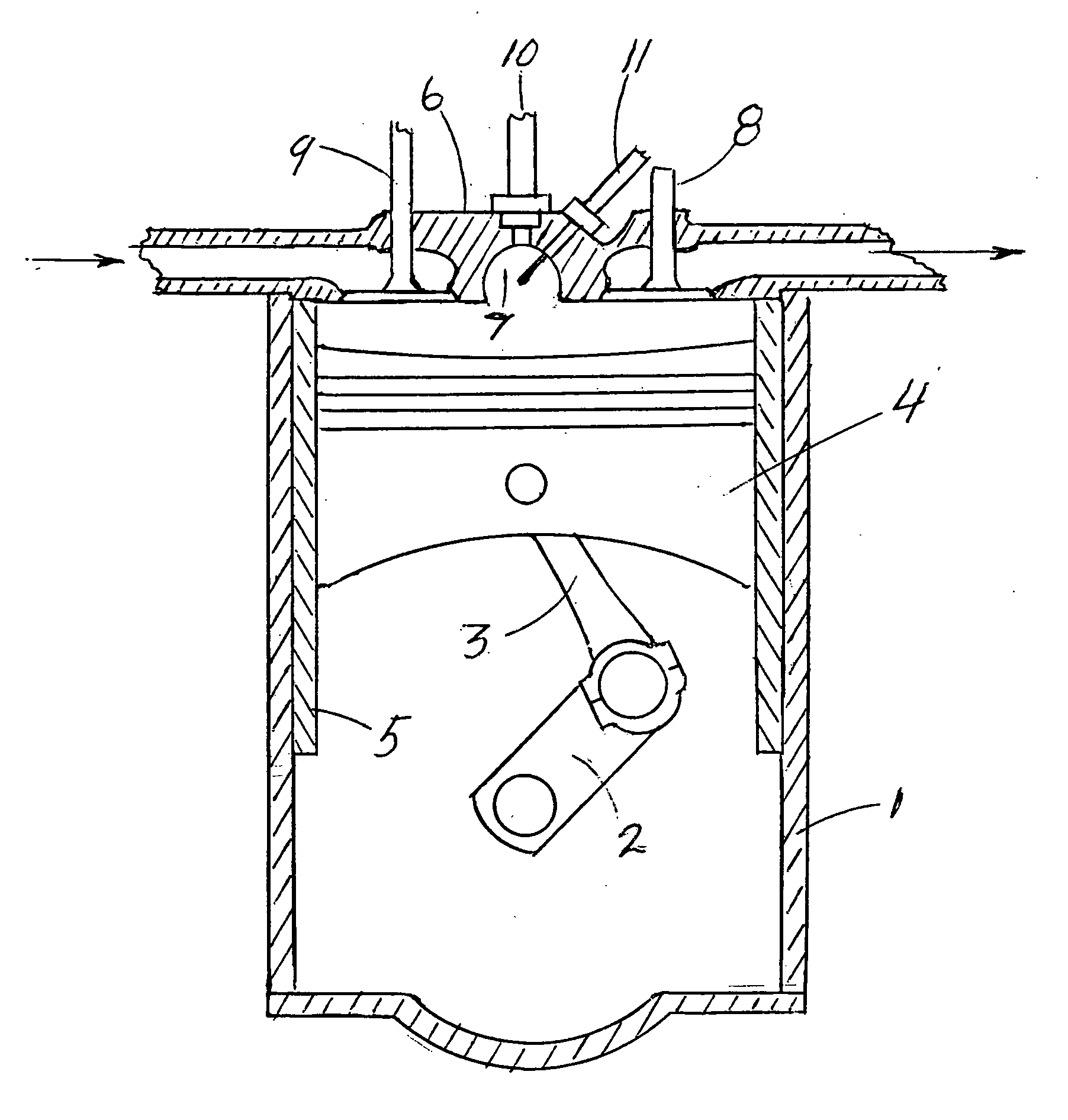
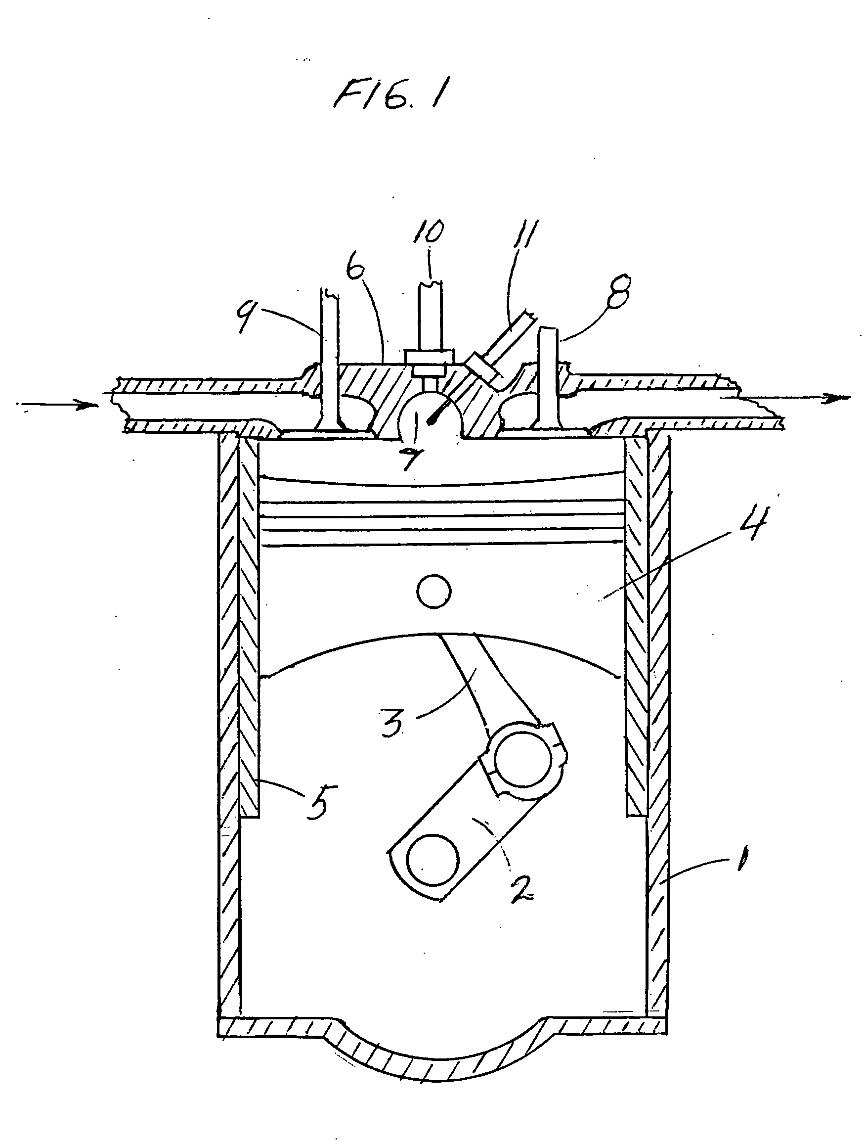
[0011] With reference to FIG. 1, a four-stroke version of an internal steam engine includes a crankcase 1, a rotary crankshaft 2, connected to rod 3, affixed to piston 4, cylinder 5, cylinder head 6, pre-chamber 7, exhaust valve 8, intake valve 9, injector 10 and heating element 11.

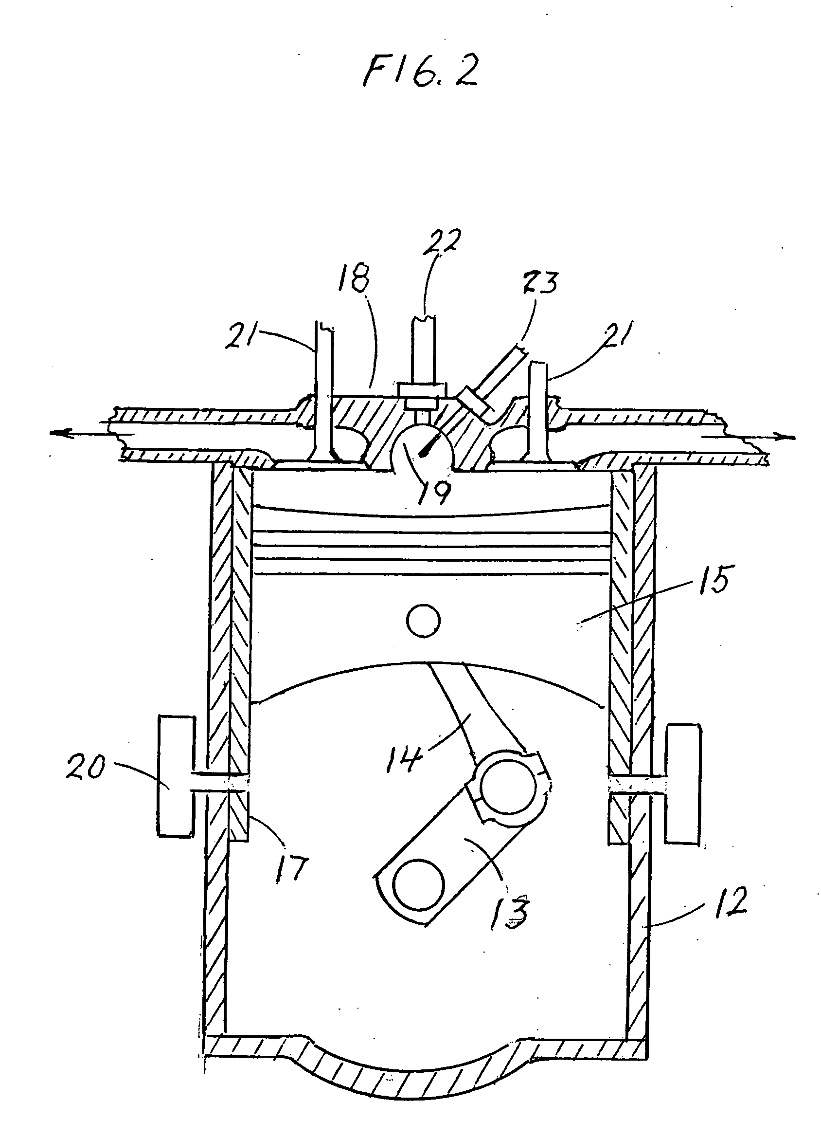
[0012] With reference to FIG. 2, a two-stroke version of an internal steam engine includes a crankcase 12, a rotary crankshaft 13, rod 14, piston 15, cylinder 17, cylinder head 18, pre-chamber 19, air intake ports 20, exhaust valve 21, injector 22, and heating element 23.

[0013] In a four-stroke embodiment of the invention, the cycle of the internal steam engine comprises six main stages which are air intake, compression, steam generation, expansion, exhaust and condensation as outlined schematically in the following figures.

[0014]FIG. 3—Air Intake: The piston is moving from top dead center to bottom dead center to draw in fresh air through the opening of the intake valve.

[0015]FIG. 4—Compression: Whil...


PUM


Abstract

An internal steam engine comprising one or more cylinders containing pistons, injectors and heating means. Air is drawn into said cavities and compressed as the piston reaches top dead center. The injector means spray the charge of heated compressed air with a non-combustible liquid which is vaporized under constant pressure followed by expansion and power stroke by the piston. The exhaust of the air mixture from the piston cavity is released through the liquid supply tank where the vapor is condensed and recycled to complete a closed operating cycle. A new charge is taken in at the end of the exhaust following either a four- or two-stroke engine process. The heating means are controlled by the cylinder temperature and activated to provide heat to the compression as required. In difference to a conventional steam engine, which generates steam from water in a boiler outside the working cylinder, the internal steam engine vaporizes water intermittently inside the working cylinder and exclusively in each compressed air charge to initiate a power stroke by the piston.

Description

BACKGROUND OF THE INVENTION [0001] The present invention relates to two- and four-stroke internal combustion engines in which useful work is generated from combustion of oxidizer and fuel which expansion acts upon the top of an reciprocating piston. Such engines use either spark ignition or compression ignition for the combustion of the air-fuel mixture. The basic components of the engines include the engine block, cylinder head, cylinders, pistons, valves, crankshaft and flywheel. Such combustion engines are fueled by refined petroleum products and constitute the main power source for vehicle locomotion in the world today. The sheer quantity of oil being burnt for this purpose represent a growing threat to our environment by emission of carbon dioxide which, greenhouse gas, allegedly is the main contributor to the present trend of global warming. The world demand for oil also gives rise to geopolitical supply problems involving national security and economic instability. [0002] In ...

Claims


Application Information

Patent Timeline
IPC IPC(8): F01K3/00F01K1/00
CPCF01K21/02
Inventor FLATER, ANDERS HARALD
Owner FLATER ANDERS HARALD
Why Eureka
Try Eureka