Detection Cartridges, Modules, Systems and Methods

a technology of detection cartridges and cartridges, applied in the field of detection cartridges and methods, can solve the problems of reducing the sensitivity of acousto-mechanical detection systems, affecting the accuracy of target analytes, and difficulty in controlling both volumetric flow rate and fluid flow front progression, so as to facilitate the detection of different target analytes, reduce or prevent selective attachment, the effect of preventing contamination of the interior volum

Inactive Publication Date: 2007-10-25
3M INNOVATIVE PROPERTIES CO
View PDF76 Cites 53 Cited by
  • Summary
  • Abstract
  • Description
  • Claims
  • Application Information

AI Technical Summary

Benefits of technology

[0016] Controlled presentation may also include control over the fluid flow front progression across the detection surface. The “flow front”, as that term is used herein, refers to the leading edge of a bolus of fluid moving across a detection surface within a detection chamber. A potential advantage of control over the flow front progression is that preferably all of the detection surface may be wetted out by the sample material, i.e., bubbles or voids in the fluid that could occupy a portion of the detection surface may preferably be reduced or eliminated.
[0017] Controlled presentation may also encompass volumetric flow control through a detection chamber that, in some embodiments of the present invention, may be achieved by drawing fluid through the detection chamber using, e.g., capillary forces, porous membranes, absorbent media, etc. Controlling the flow rate of sample material over the detection surface may provide advantages. If, for example, the flow rate is too fast, target analyte in the sample material may not be accurately detected because selective attachment may be reduced or prevented. Conversely, if the flow rate is too slow, excessive non-specific binding of non-targeted analytes or other materials to the detection surface may occur, thereby potentially providing a false positive signal. The present invention also provides sealed modules that may be selectively incorporated into, e.g., a detection cartridge, to facilitate the detection of different target analytes within the detection cartridge. Before use, the modules may preferably be sealed to prevent materials located therein from escaping and / or to prevent contamination of the interior volume of the modules. The modules may preferably include two or more isolated chambers in which different constituents may be stored before they are introduced to each other and to the detection cartridges. The introduction and mixing of the different constituents, along with their introduction into the detection cartridge (and, ultimately, the sensor) may be controlled using the modules and actuators. Isolated storage of many different reagents may greatly enhance the shelf-life of materials that may be used to assist in the detection of target analytes. Some reagents that may benefit from isolated dry storage conditions may include, e.g., lysing reagents, fibrinogen, assay-tagged magnetic particles, etc.
[0018] The modules may be selected and attached to the detection cartridge by the manufacturer or, in some instances, by an end user. The flexibility offered to an end user to, essentially, customize a detection cartridge at the point-of-use may offer additional advantages in terms of economy and efficiency. For example, different modules containing different reagents, buffers, etc. may be supplied to the end-user for their selective combination of modules in a detection cartridge to perform a specific assay for a specific target analyte.

Problems solved by technology

One technical problem that may be associated with many sensors is that the flow rate and / or flow front progression across the detection surface of a sensor may affect accurate detection of target analytes.
Control over both volumetric flow rate and fluid flow front progression may, however, be difficult if the detection surface of the sensor is flat because such surfaces may be subject to the formation of voids, bubbles, etc. due to surface tension in liquids moving across a such a surface.
The liquid carrier may undesirably reduce the sensitivity of the acousto-mechanical detection systems.
Furthermore, the selectivity of such sensors may rely on properties that cannot be quickly detected, e.g., the test sample may need to be incubated or otherwise developed over time.
Selective binding of known target biological analytes to detector surfaces can, however, raise issues when the sensor used relies on acousto-mechanical energy to detect the target biological analyte due to the size and relative low level of mechanical rigidity of many or most biological analytes.
This issue may be especially problematic in connection with shear-horizontal surface acoustic wave detection systems.
What has not heretofore been appreciated is that the effective wave field of the sensors is significantly limited relative to the size of biological analytes to be detected.
As a result, the effect of acousto-mechanical energy traveling within the effective wave field above a sensor on the total mass of the biological analytes can be significantly limited.
In many instances, target biological analytes attached to the surfaces of such sensors cannot be accurately distinguished from the liquid medium used to deliver the agents to the detector.
Although not wishing to be bound by theory, it is theorized that the relative lack of mechanical rigidity in biological analytes attached to a detection surface, i.e., their fluid nature, may significantly limit the amount of mass of the biological analytes that is effectively coupled to the detection surface.
As a result, the ability of an acousto-mechanical biosensor (e.g., a LSH-SAW biosensor) to effectively detect the presence or absence of target biological analytes can be severely limited.

Method used


Image

  • Detection Cartridges, Modules, Systems and Methods
  • Detection Cartridges, Modules, Systems and Methods
  • Detection Cartridges, Modules, Systems and Methods

Examples


Embodiment Construction

[0055] In the following detailed description of exemplary embodiments of the invention, reference is made to the accompanying figures of the drawings which form a part hereof, and in which are shown, by way of illustration, specific embodiments in which the invention may be practiced. It is to be understood that other embodiments may be utilized and structural changes may be made without departing from the scope of the present invention.

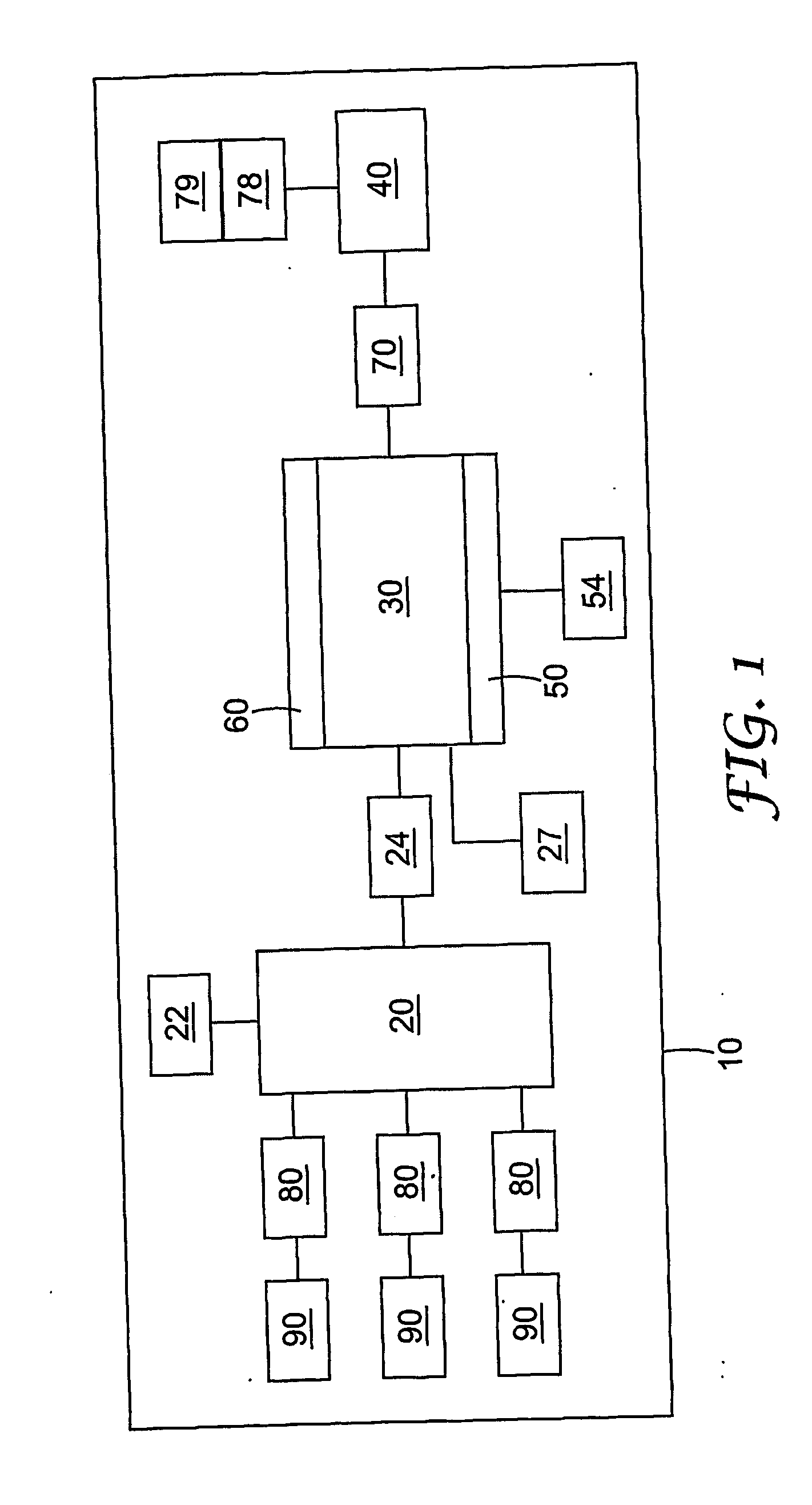
[0056] In one aspect, the present invention provides detection cartridges that include an integrated sensor and fluid control features that assist in selective delivery of a sample analyte to the sensor. The exemplary detection cartridge 10 depicted schematically in FIG. 1 includes a staging chamber 20, detection chamber 30, waste chamber 40, sensor 50, volumetric flow control feature 70, and modules 80. In general, the detection cartridge 10 of FIG. 1 may be described as having an interior volume that includes the staging chamber 20, detection cham...


PUM

PropertyMeasurementUnit
diameteraaaaaaaaaa
volumesaaaaaaaaaa
volumesaaaaaaaaaa

Abstract

Detection cartridges and associated components, as well as methods of using the same that provide sample materials to a sensor for detection are disclosed. Among the components that may be used in connection with the detection cartridges of the present invention are, e.g., input modules, fluid flow front control features, and volumetric flow rate control features. The modules may include one or more chambers containing different constituents for mixing and/or delivery into a detection cartridge.

Description

RELATED APPLICATIONS [0001] The present application claims priority to U.S. Provisional Patent Application Ser. No. 60 / 533,169, filed on Dec. 30, 2003, which is hereby incorporated by reference in its entirety.GOVERNMENT RIGHTS [0002] The U.S. Government may have certain rights to this invention under the terms of DAAD 13-03-C-0047 granted by Department of Defense.[0003] The present invention relates detection cartridges and methods for detecting one or more target analytes in fluid sample material. [0004] Unlike classical clinical assays such as tube and slide coagulase tests, the detection cartridges of the present invention employ an integrated sensor. As used herein “sensor” refers to a device that detects a change in at least one physical property and produces a signal in response to the detectable change. The manner in which the sensor detects a change may include, e.g., electrochemical changes, optical changes, electro-optical changes, acousto-mechanical changes, etc. For exa...

Claims


Application Information

Patent Timeline
Patent Type & Authority Applications(United States)
IPC IPC(8): G01N33/487B01L3/00C07C311/51C07D207/46C07D275/06G01N29/02G01N33/543
CPCB01L3/502723G01N2291/0427B01L3/502746B01L3/523B01L2200/04B01L2200/0684B01L2200/10B01L2200/16B01L2300/06B01L2300/0663B01L2300/0672B01L2300/069B01L2300/161B01L2400/0406B01L2400/0478B01L2400/0683B01L2400/086B01L2400/088C07C311/51C07D207/46C07D275/06G01N29/022G01N29/222G01N29/2462G01N2291/0255G01N2291/0256G01N2291/02881G01N2291/0422G01N2291/0423G01N2291/0426B01L3/50273B01L3/00G01N29/02G01N33/543
Inventor CARTER, CHAD J.DODGE, LARRY H.GASON, SAMUEL J.JOHNSTON, RAYMOND P.SMITH, JEFFREY D.WOOD, KENNETH B.
Owner 3M INNOVATIVE PROPERTIES CO
Why Eureka
Try Eureka