Gas Treatment Device

a gas treatment device and gas treatment technology, applied in the field can solve the problems of difficult compactness of gas treatment devices, inability to accelerate turbulence on dust collection electrodes, inability to use the effect to improve agglomeration, growth, dust collection, etc., to facilitate the contact of charged particles, reduce the time required, and increase the agitation effect in the cross-section of flow passages

Inactive Publication Date: 2007-10-25
AKIRA MIZUNO +1
View PDF24 Cites 17 Cited by
  • Summary
  • Abstract
  • Description
  • Claims
  • Application Information

AI Technical Summary

Benefits of technology

[0046] As described hereinbefore, according to the gas treatment device of the present invention, as it is composed by providing means of accelerating turbulence in the vicinity of or on the facing surface of the dust collecting electrode, which is non-discharge electrode facing to corona electrode, to accelerate gas turbulence in the vicinity of the facing surface of the dust collecting electrode, so the agitation effect in the flow passage cross-section can be increased, by said means due to acceleration of gas turbulence in the flow passage, especially, in the vicinity of the facing surface of the dust collecting electrode.
[0047] Therefore, it can be planed to reduce the period of time necessary for chargi

Problems solved by technology

As the result, there is a problem that the gas treatment device is difficult to be made compact.
Besides, since such convex shape and so on are not for the object of turbulence acceleration, they are all provided on the discharge electrode and not on the dust-collecting electrode side.
Consequently, it is impossible to accelerate turbulence on the dust-collecting electrode where particles are agglomerated and grown.
Therefore, it is impossible to use the effect to improve agglomeration, growing, dust collection, and capture and so on by turbulence acceleration.
Though the structure of this apparatus may be effective when chemical reactions of g

Method used


Image

  • Gas Treatment Device
  • Gas Treatment Device
  • Gas Treatment Device

Examples


first embodiment

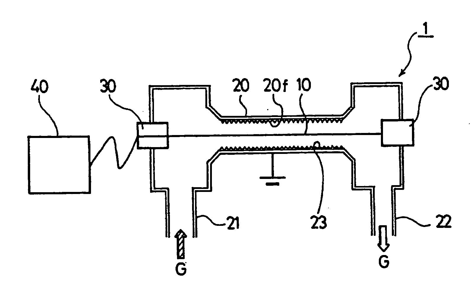
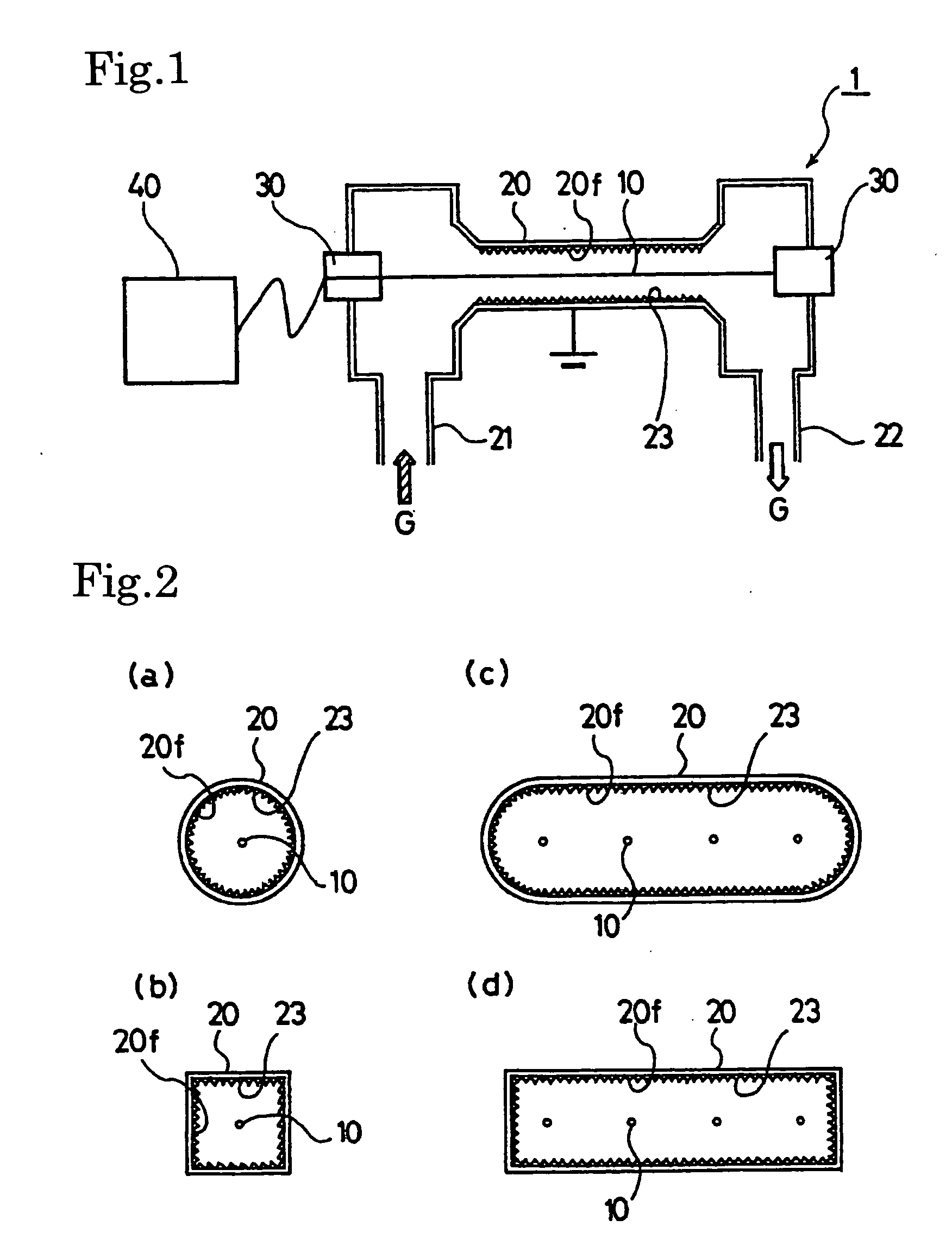
[0076] Now, the gas treatment device in embodiments according to the present invention shall be described referring to drawings. As shown in FIG. 1 and FIG. 2, a gas treatment device 1 of the present invention comprises a corona electrode 10 for applying a high voltage for generating corona discharge and a cylindrical body 20 surrounding this corona electrode and becoming a dust-collecting electrode.

[0077] The corona electrode 10 may be an electrode that has high level of electric field concentration factor. The corona electrode 10 is formed using a linear (wire-like) or rod-shaped electrode, such as a fine electrode, a square electrode and an electrode with uneven structure. The cylindrical body 20 is made of conductive material and surrounds with the corona electrode 10. In addition, the cylindrical body 20 is provided with a gas inlet part 21 on the upstream side, and a gas outlet part 22 on the downstream side.

[0078] This corona electrode 10 and the cylindrical body 20 are comp...

second embodiment

[0121] Now, a gas treatment device shall be described.

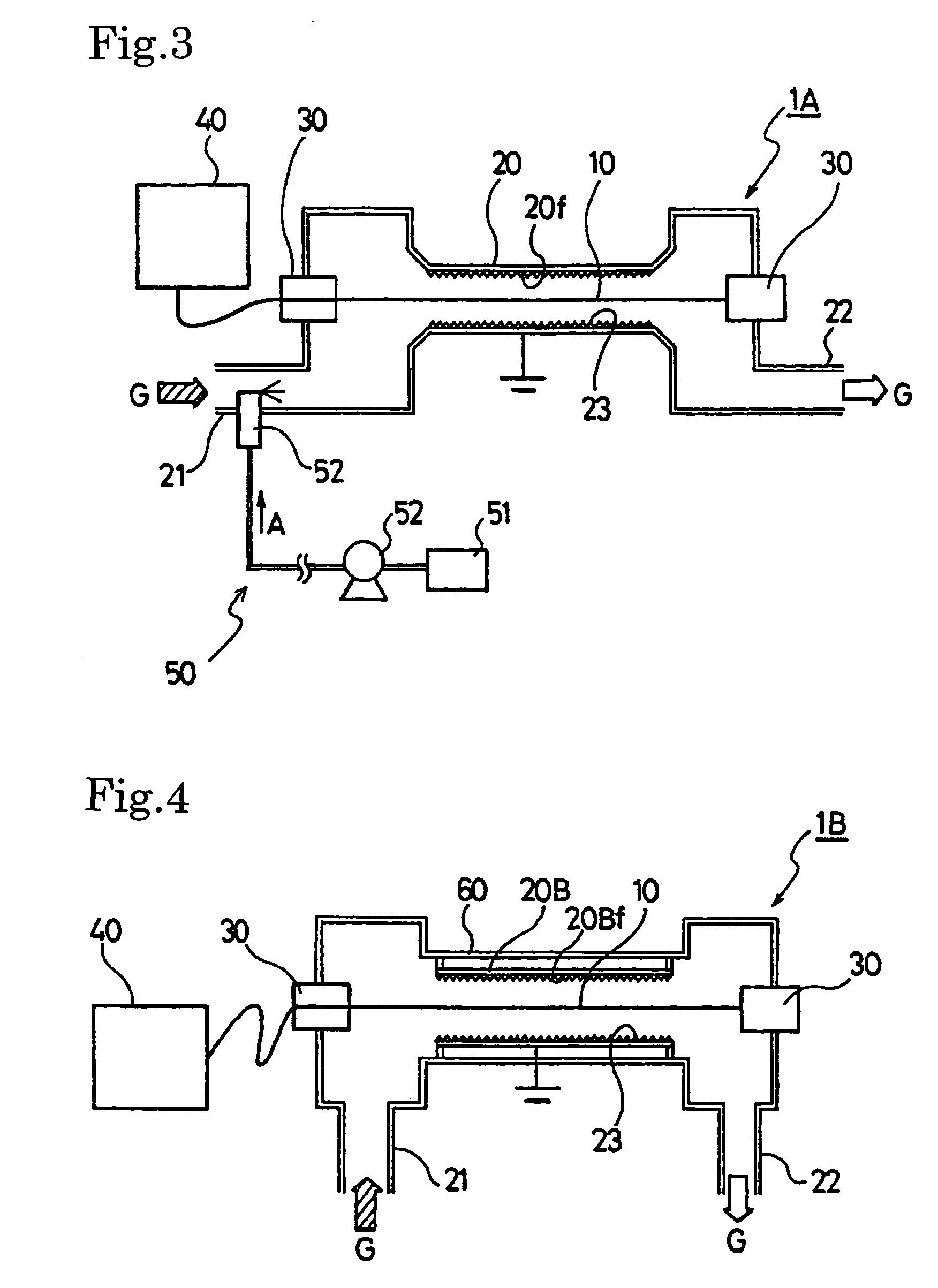
[0122] The gas treatment device 1A of the second embodiment shown in this FIG. 3 is composed to provide an additive supply means 50 at a gas inlet part 21. This additive supply means 50 supplies the gas G to be introduced into the interior of the cylindrical body 20 with an additive 20 for agglomerating or growing components in the gas G, at a gas inlet part 21. As this additive A, water, hydrocarbons, surface-active agents and, in case of gas for inner combustion engine, fuels and so on can be used. Also, as for concrete composition of additive supply means 50, there is a composition where an injector for receiving the additive A supplied from the additive tank or fuel tank and spraying into the interior of the gas inlet part 21. Except for this composition, the composition of the gas treatment device 1A is same as the gas treatment device 1 of the first embodiment.

[0123] According to the additive supply means 50 of the gas tr...

third embodiment

[0124] Now, a gas treatment unit shall be described.

[0125] The gas treatment device 1B of the third embodiment shown in FIG. 4 to FIG. 7 is composed to shape a dust-collecting electrode 20B with a sheet body facing a corona electrode 10 and to enclose this sheet body together with said corona electrode 10 by a gas-impermeable cylindrical body 60. Then, it is so composed to pass the gas G in this cylindrical body 60. FIG. 4 and FIG. 5 show a composition where the dust-collecting electrode 20B is made from a single sheet body or a pair of parallel sheet body to the corona electrode 10. And, FIG. 6 and FIG. 7 show a composition where the corona electrode 10 and the parallel sheet body dust-collecting electrode 20B are formed into a multiple stacking structure.

[0126] And, according to present invention, the dust-collecting electrode 20B of the gas treatment device 1B of this third embodiment is provided with means for accelerating turbulence 23 on the facing surface 20Bf thereof or in...


PUM


Abstract

Gas treatment equipment (1) comprising a corona electrode (10) and a dust-collection electrode (20) facing the corona electrode (10), and forming corona discharge in gas (G) passing between the corona electrode (10) and the dust-collection electrode (20) by applying a high voltage between them to thereby agglomerate or collect components in the gas (G), wherein a means (23) for accelerating turbulence of the gas (G) in the vicinity of the surface (200 of the dust-collection electrode (20) facing the corona electrode (10) is provided on the opposing surface (20f) or in the vicinity thereof.

Description

BACKGROUND OF THE INVENTION [0001] 1. Field of the Invention [0002] The present invention concerns a gas treatment device for purifying exhaust gas such as industrial gas, power plant gas, automobile gas and so on, or purifying gas emitted at various manufacturing plant, medical facilities and so on, by using corona discharge. [0003] 2. Description of the Related Art [0004] An electrostatic agglomerator, an electrostatic dust collector or the like is used as exhaust gas treatment device for industrial gas, power plant gas, automobile gas and so on, and for gas emitted at various manufacturing plant, medical facilities and so on. In these equipments, by applying a high voltage between a corona electrode and a dust-collecting electrode, corona discharge is generated to charge floating fine particles such as particulate matters (PMs) in gas. Then, the charged particles are attracted to the dust-collecting electrode to be agglomerated, grown, or caught or to be captured by electrostatic...

Claims


Application Information

Patent Timeline
IPC IPC(8): B03C3/45B01D53/32B01D53/94F01N3/02B03C3/00B03C3/36B03C3/40B03C3/49B03C3/60F01N3/01F01N3/08F01N3/18F01N3/24
CPCB01D53/32B01D2258/01B01D2259/818B03C3/36Y02T10/20B03C2201/30F01N3/01F01N2240/20B03C3/45Y10S55/38Y02T10/12F01N3/02
Inventor NAITO, KENTASENBAYASHI, SATORUHAMADA, YUICHIMIZUNO, AKIRAKASAI, JUNICHITAMURA, YOSHINOBU
Owner AKIRA MIZUNO
Why Eureka
Try Eureka