
Method of making an article

a technology of making an article and a mask is applied in the field of making an article, which can solve the problems of limited use of masks in ferrous metallic molds, painting and contaminating the first region, and affecting the safety of pedestrians/occupants, etc., and achieves the effects of simple and cost-effective, easy removal, and simple control of pressur

Active Publication Date: 2007-10-25
BASF CORP
View PDF26 Cites 14 Cited by
  • Summary
  • Abstract
  • Description
  • Claims
  • Application Information

AI Technical Summary

Benefits of technology

The present invention provides a method of making an article with two or more layers using a mask in a mold. The mask is independent from the force of gravity, easy to manipulate, and compatible with non-metallic molds. The method includes applying pressure to the mask to retain it in place and using preformed parts to avoid the need for a mold. The technical effect is the ability to make an article with a distinct line between different colors and with improved sealing between the mask and the mold surface.

Problems solved by technology

Unfortunately, the mask can be lifted up and off of the bottom of the mold cavity during spraying off the first paint composition, thereby painting and contaminating the first region with the first paint composition.
In addition, placement of the mask in the mold cavity is limited due to the dependence on the force of gravity to hold the mask in place.
Due to the reliance on magnets, the mask is limited to use in ferrous metallic molds.
In addition, precise incremental movement of the mask once magnetically attached to the surface is difficult due to the magnetic attraction between the mask and the mold.
Both methods of the '303 and '390 patents also suffer from a lack of a complete seal between the mask and the surface of the mold, particularly upon a textured or patterned surface of the mold at an interface between the first and second regions.
The lack of seal results in a non-distinct line between the first and second colors of the skin.

Method used


Image

  • Method of making an article
  • Method of making an article
  • Method of making an article

Examples


Embodiment Construction

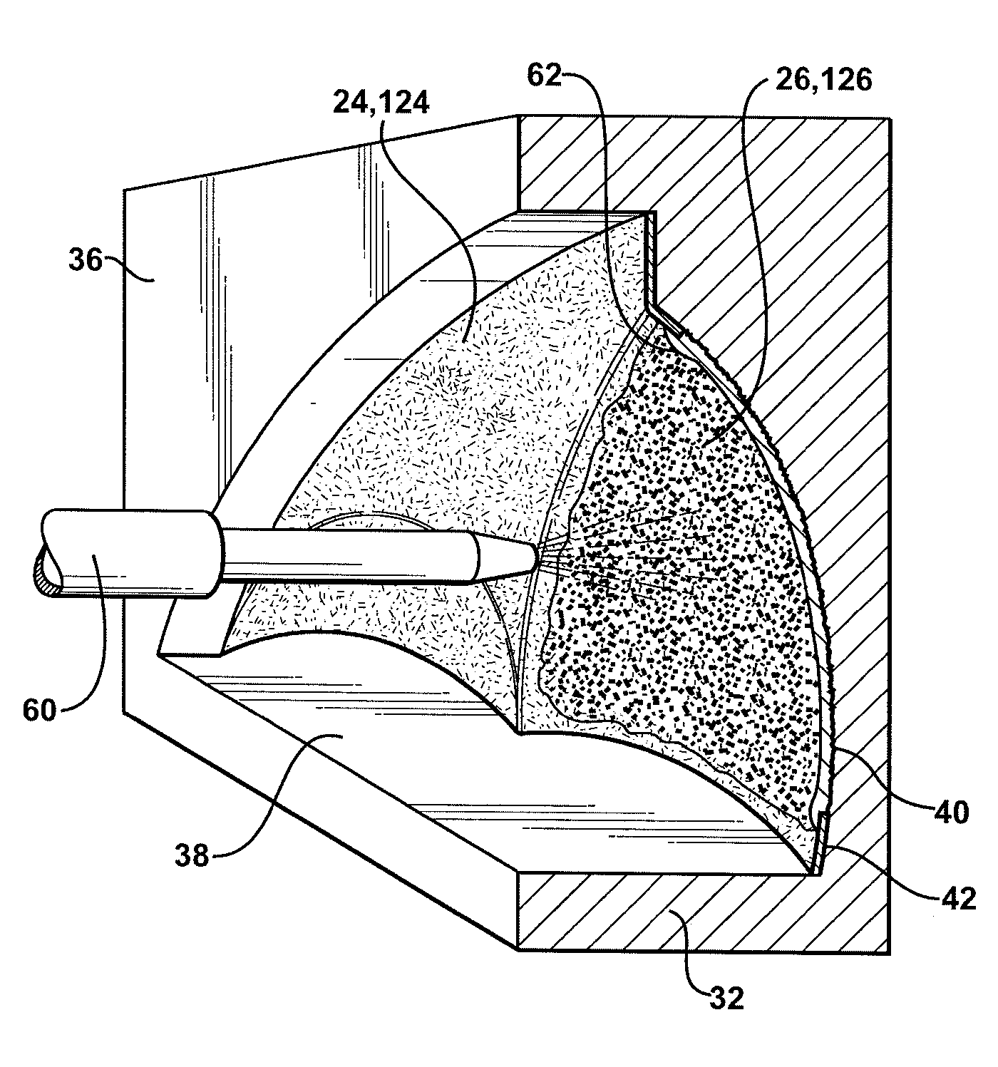
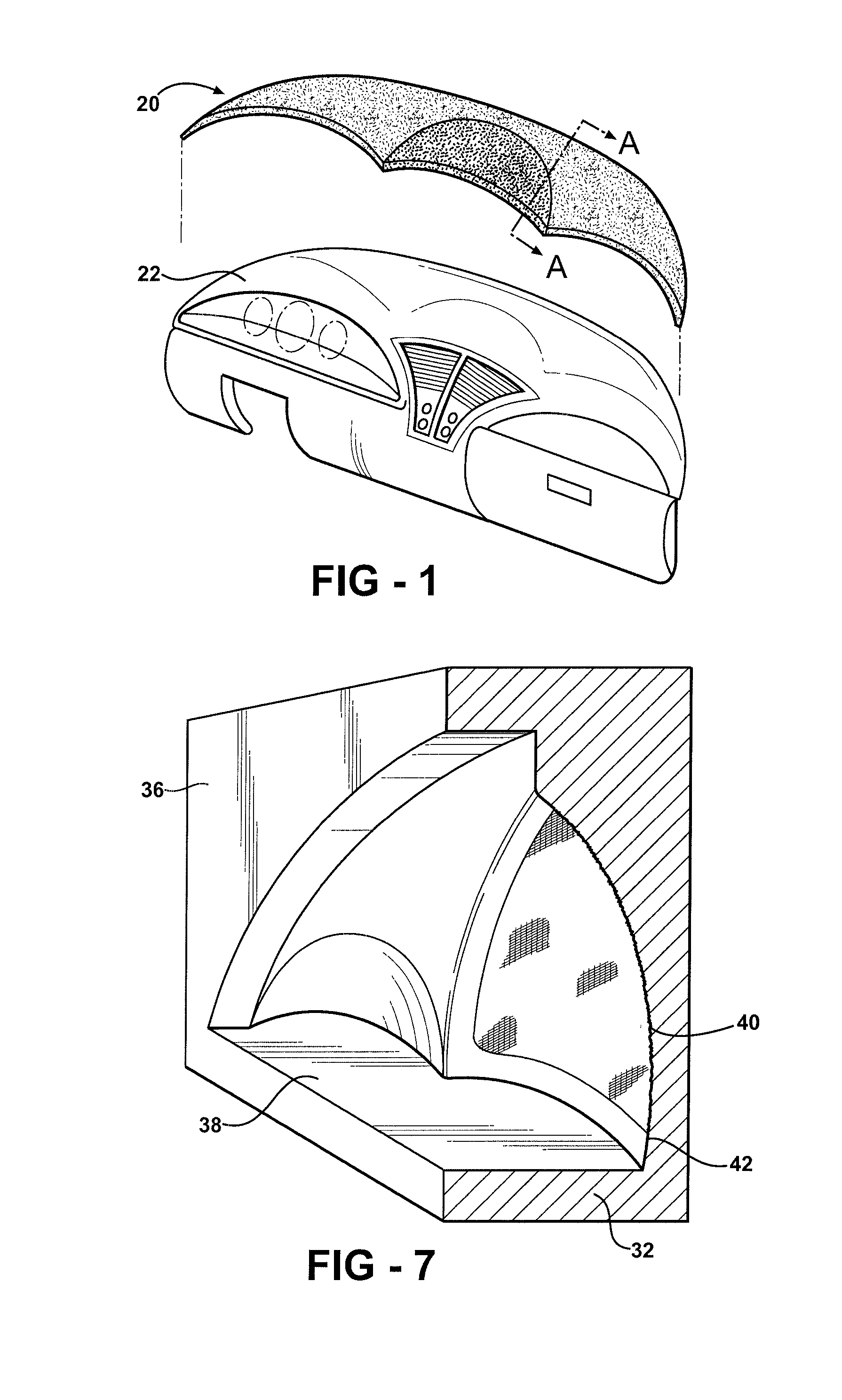
[0028] Referring to the Figures, wherein like numerals indicate like parts throughout the several views, an article made in accordance with a method of the present invention is shown generally at 20.

[0029] In one embodiment, as shown in FIG. 1, the article 20 is a skin for covering an instrument panel 22 of a vehicle. While the article 20 is shown as a skin for covering the instrument panel 22, it is to be appreciated that in other embodiments, the article 20 may be further defined as at least one of a headrest, a trim panel, a seat, a pillar trim panel, an instrument panel, a door panel, and an armrest.

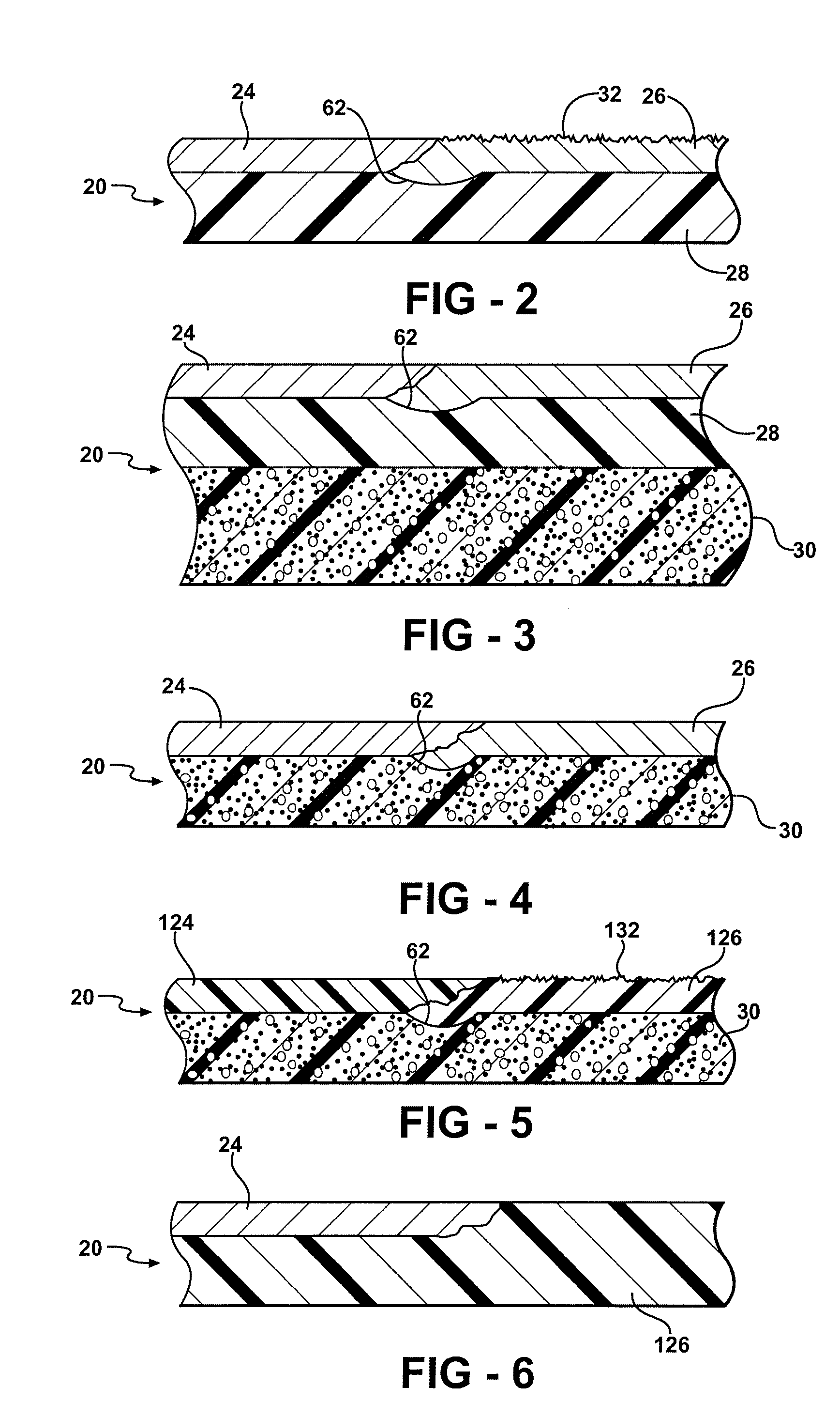
[0030] Referring to FIGS. 2-6, the article 20 includes a first layer 24, 124 and a second layer 26, 126. In one embodiment, as shown in FIGS. 2-5, the first layer 24, 124 and the second layer 26, 126 are adjacent to each other, i.e. the layers are substantially co-planar. In one embodiment, the article 20 may have a distinct line between the first layer 24, 124 and the second layer...


PUM

PropertyMeasurementUnit
pressureaaaaaaaaaa
elastomericaaaaaaaaaa
compositionaaaaaaaaaa

Abstract

A mask is used to make an article having two or more layers. The layers are formed from either a paint or polyurethane elastomer composition. The article is made in a mold including a surface defining a mold cavity and having a first and second effect region. For the method, a mask is placed into the mold cavity adjacent the first effect region. Pressure is applied to the mask to retain the mask adjacent the first effect region. A first composition is applied into the mold cavity to form a first layer adjacent the second effect region. The mask is removed from the first effect region. A second composition is applied into the mold cavity to form a second layer adjacent the first effect region. Benefits of pressure applied to a mask are also realized when making the article from a preformed part using the mask outside of a mold.

Description

FIELD OF THE INVENTION [0001] The present invention generally relates to a method of making an article. More specifically, the present invention relates to a method of making an article having two or more layers. The article may be, for example, a headrest, a trim panel, a seat, a pillar trim panel, an instrument panel, a door panel, or an armrest. DESCRIPTION OF THE RELATED ART [0002]“Masking-off” or “masking” is a common method of protecting a surface from receiving paint when paint is being applied to an adjacent surface. In manufacturing, masking may be used to make a multilayer or multi-tone skin having two or more layers. For example, instrument panels, seats, headrests, armrests, trim panels, pillar panels, and door panels for vehicles often include a skin that provides an aesthetically pleasing covering. The skin commonly includes a relatively thin outer paint layer with a thicker polyurethane elastomeric backing layer. The outer paint layer provides a desired color and UV d...

Claims


Application Information

Patent Timeline
Patent Type & Authority Applications(United States)
IPC IPC(8): B29C44/04
CPCB29C44/0469B60R13/02B60R21/04B60R13/025B60R13/0256B60R13/0243
Inventor DEBIASI, DAVIDVARUGHESE, MATHEW P.PAVLINAC, JON P.
Owner BASF CORP
Learn More