Plasma generating electrode and plasma reactor

Inactive Publication Date: 2007-10-25
NGK INSULATORS LTD +1
View PDF9 Cites 6 Cited by
  • Summary
  • Abstract
  • Description
  • Claims
  • Application Information

AI Technical Summary

Benefits of technology

[0019] The plasma generating electrode according to the present invention allows simple and reliable electrical connection of each unit electrode. Since the plasma reactor acc

Problems solved by technology

According to the above plasma generating electrode, since the conductive terminal is disposed on the end face of the unit electrode, the area of the connection portion of the conductive terminal is reduced to a large extent, whereby

Method used


Image

  • Plasma generating electrode and plasma reactor
  • Plasma generating electrode and plasma reactor
  • Plasma generating electrode and plasma reactor

Examples


example 1

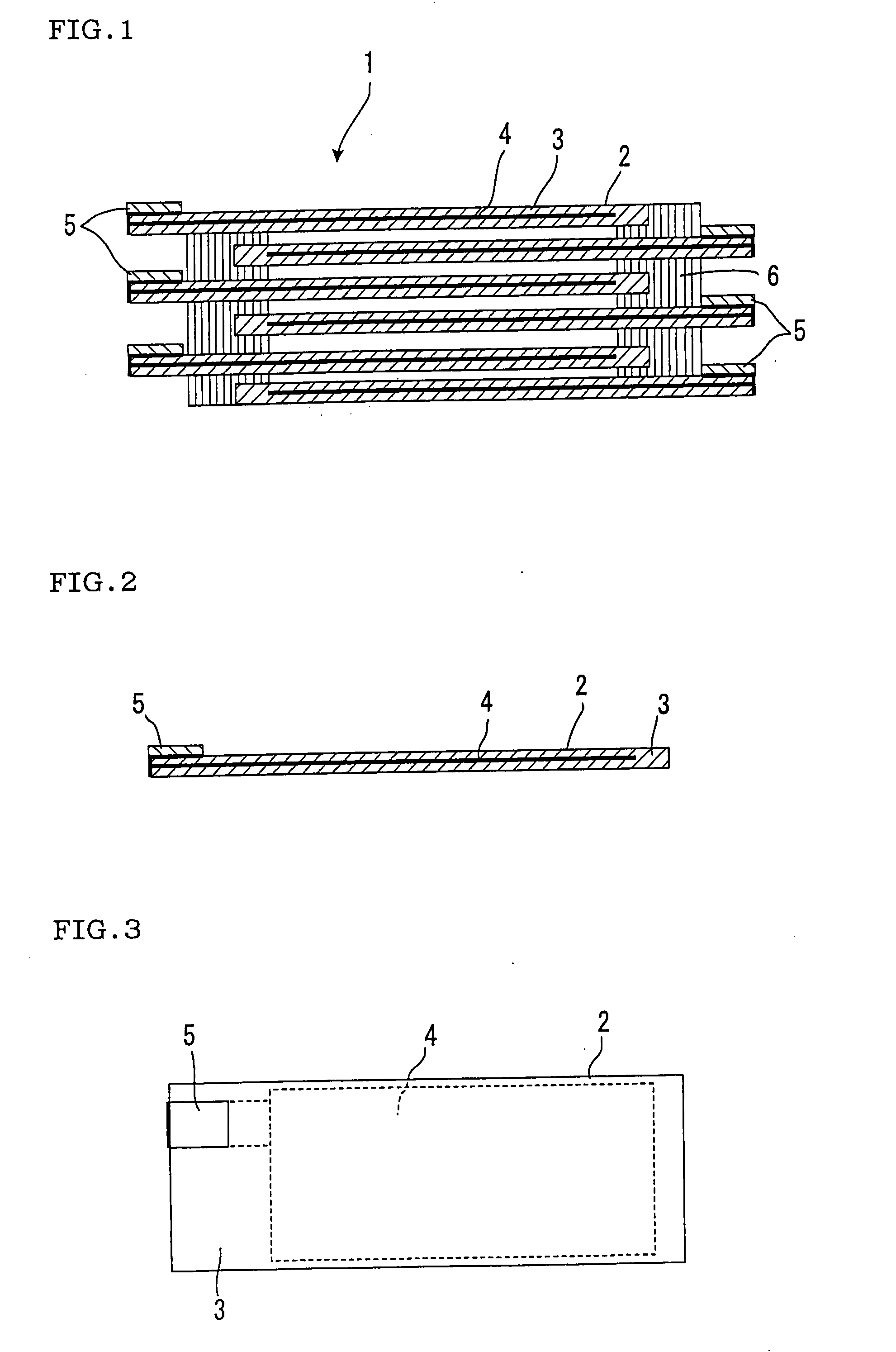
[0088] A slurry for forming a ceramic green sheet was prepared using an aluminum oxide powder with a purity of 93 mass %. A ceramic green sheet in the shape of a tape having a rectangular surface shape (length: 100 mm, width: 50 mm) and having a thickness of 0.5 mm was formed using the resulting slurry. A pair of the resulting ceramic green sheets was used. A conductive paste using tungsten was printed on one side of one of the pair of ceramic green sheets to a length of 78 mm, a width of 48 mm, and a thickness of 0.01 mm to form a conductive film.

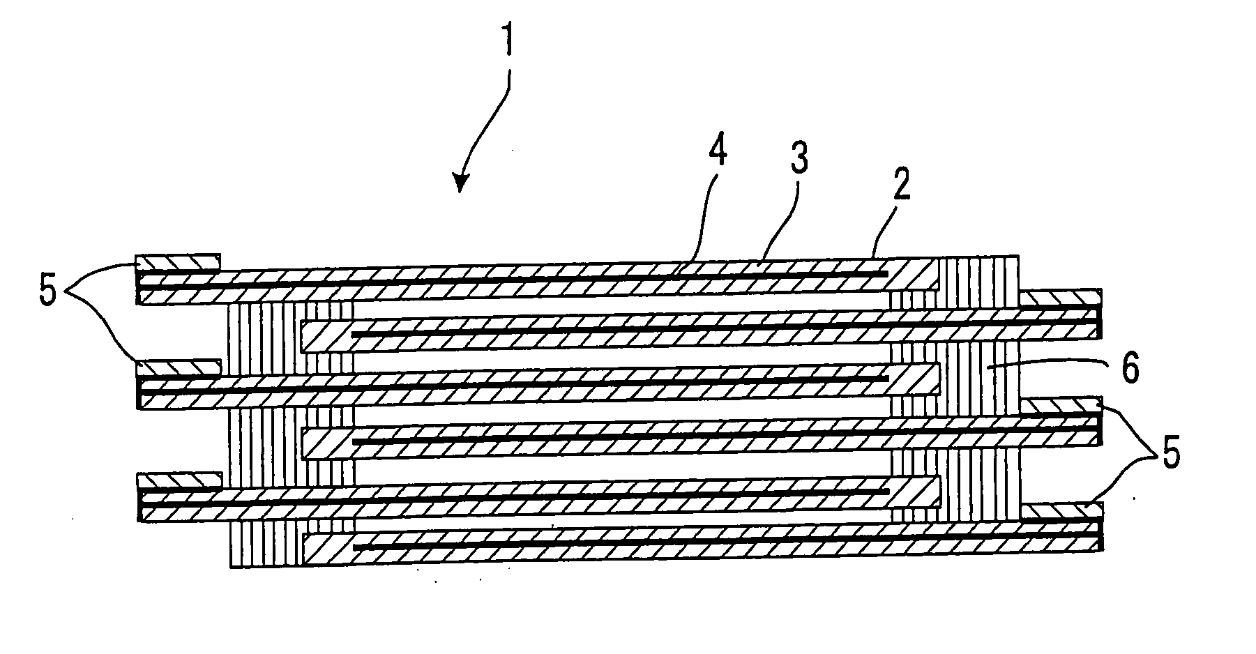
[0089] The conductive film was formed to extend to one end at a width of 10 mm in the same manner as in the plasma generating electrode 1 shown in FIG. 3 so that an electrode terminal with a length of 10 mm could be formed on the end of the unit electrode.

[0090] The pair of ceramic green sheets thus obtained was stacked and integrated so that the conductive film was covered to form an unfired unit electrode. A conductive paste using tung...


PUM


Abstract

In a plasma generating electrode 1, at least one of opposing unit electrodes 2 includes a sheet-shaped ceramic dielectric 3 and a conductive film 4 disposed in the ceramic dielectric 3 and partially extending on the surface of the ceramic dielectric 3 opposite to the other unit electrode 2 on the end of the ceramic dielectric 3, and a conductive terminal 5 is electrically connected with the conductive film 4 extending on the surface of the ceramic dielectric 3 opposite to the other unit electrode 2 on the end of the ceramic dielectric 3. Therefore, simple and reliable electrical connection can be achieved.

Description

TECHNICAL FIELD [0001] The present invention relates to a plasma generating electrode and a plasma reactor. More particularly, the present invention relates to a plasma generating electrode and a plasma reactor capable of achieving simple and reliable electrical connection. BACKGROUND ART [0002] A silent discharge occurs when disposing a dielectric between two electrodes secured on each end and applying a high alternating current voltage or a periodic pulse voltage between the electrodes. In the resulting plasma field, active species, radicals, and ions are produced to promote reaction and decomposition of gases. This phenomenon may be utilized to remove toxic components contained in an engine exhaust gas or an incinerator exhaust gas. [0003] For example, a plasma reactor has been disclosed such as an air cleaner utilizing ozone or a plasma reactor which processes toxic components (e.g. NOx, particulate matter (PM) such as carbon particulates, HC, and CO) contained in an exhaust gas...

Claims


Application Information

Patent Timeline
IPC IPC(8): H01J7/24
CPCB01D53/32B01D2259/818H05H1/24F01N2240/28F01N3/0892H05H1/2406
Inventor FUJIOKA, YASUMASAKONDO, ATSUOMASUDA, MASAAKIDOSAKA, KENJIIWAMA, KEIZO
Owner NGK INSULATORS LTD
Why Eureka
Try Eureka