Multistrike gas discharge lamp ignition apparatus and method

Active Publication Date: 2007-10-25
XENON CORP
View PDF16 Cites 3 Cited by
  • Summary
  • Abstract
  • Description
  • Claims
  • Application Information

AI Technical Summary

Benefits of technology

[0007] Embodiments are disclosed for apparatus and methods for increasing the reliability of the discharge response in gas discharge lamps. In one embodiment, multiple ignition pulses are generated

Problems solved by technology

The high voltage pulse supplied to the ignition electrode does not always ionize the gas enough to allow the gas to conduct electricity.
For example, t

Method used


Image

  • Multistrike gas discharge lamp ignition apparatus and method
  • Multistrike gas discharge lamp ignition apparatus and method
  • Multistrike gas discharge lamp ignition apparatus and method

Examples


Example

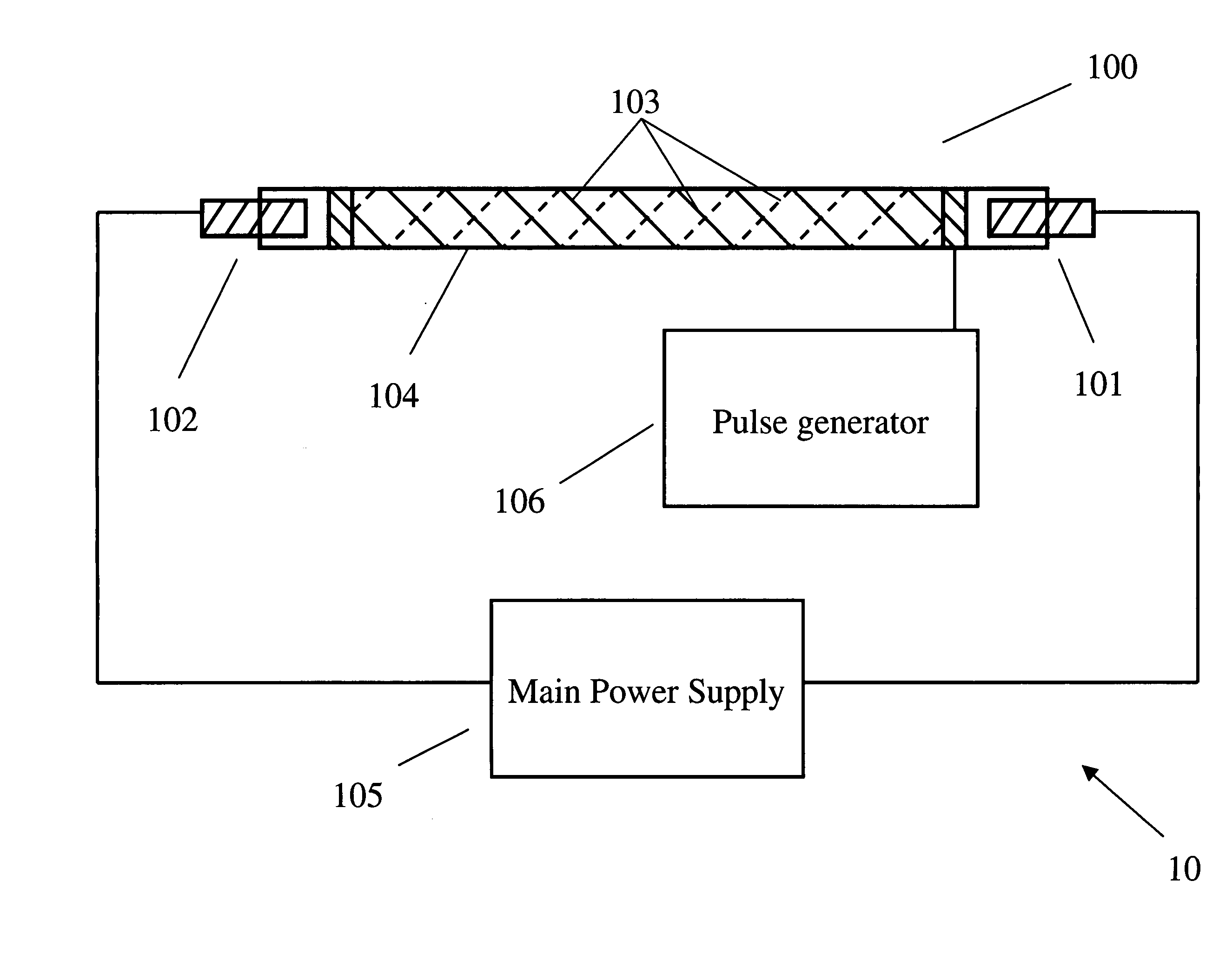
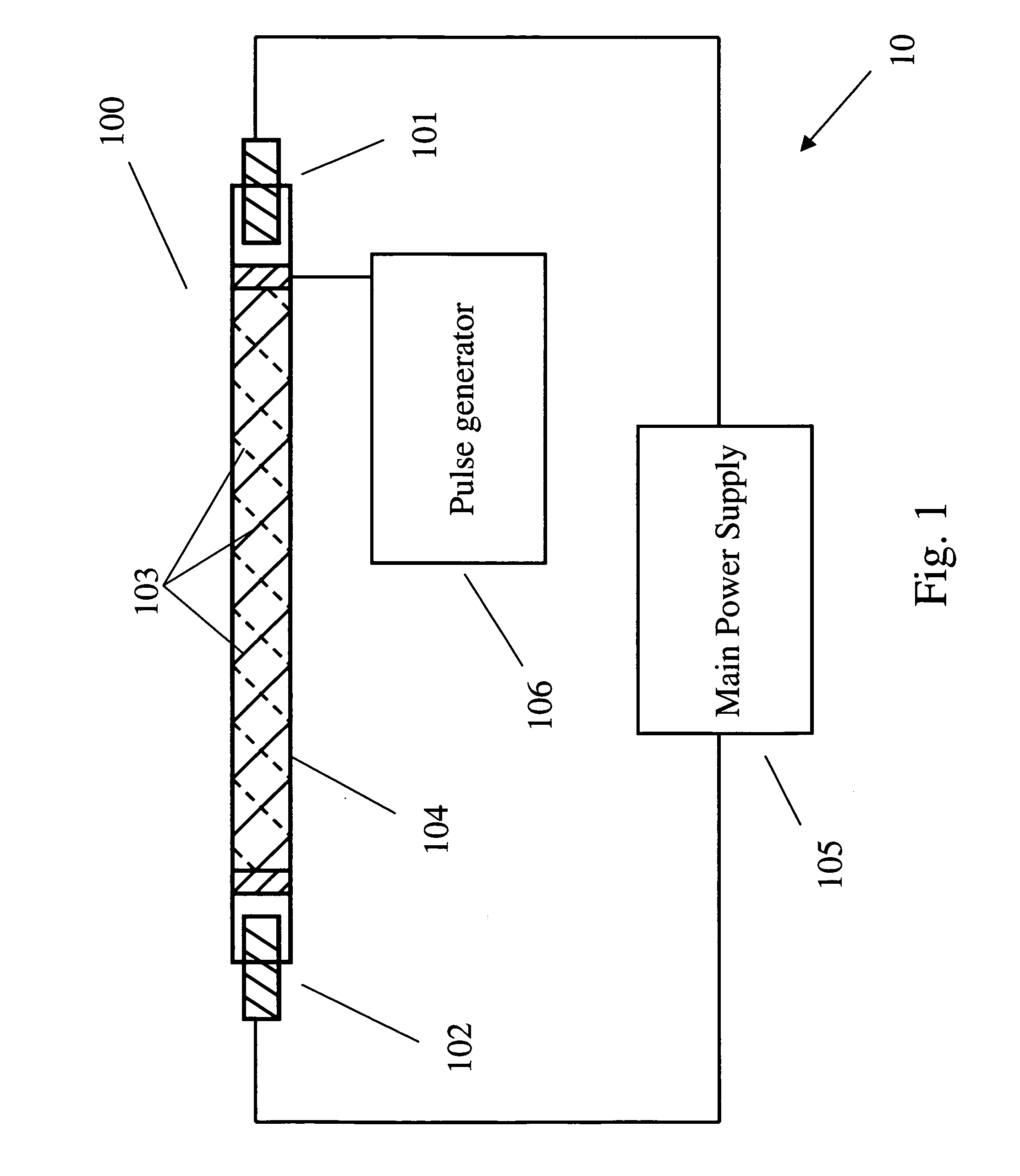
[0017]FIG. 1 is an illustration of a gas discharge lamp system 10. The system 10 includes a gas discharge lamp 100, specifically, a xenon flash lamp. The lamp 100 includes a cathode 101 and an anode 102 that extend through opposite ends of a lamp tube 104. Cathode 101 and anode 102 allow an electrical connection to be made with a gas inside lamp tube 104. The lamp also includes an ignition electrode 103, which is formed by a wire encircling a portion of lamp tube 104. The wire forming ignition electrode 103 is wrapped around the outside of a portion of lamp tube 104 as it passes from one end of lamp tube 104 to the other. In other embodiments, the cathode 101 or anode 102 may serve as the ignition electrode. In yet further embodiments, the ignition electrode may be located inside the lamp.

[0018] In order to create a discharge from lamp 100, an electrical potential is applied between cathode 101 and anode 102 by, for example, a main power supply 105. This electrical potential must b...


PUM


Abstract

A gas discharge lamp has a gas and has a cathode, an anode, and an ignition electrode. Individual discharges of a series of lamp discharges are spaced at least one millisecond from each other, and the individual discharges are generated by providing an electrical charge between the cathode and the anode and providing two or more electrical pulses to the ignition electrode. The second and following electrical pulses occur within a predetermined time of the first pulse. The electrical charge between the cathode and anode is of sufficient voltage and current to create an electrical arc between the cathode and the anode with the gas is ionized.

Description

BACKGROUND OF THE INVENTION [0001] The present invention generally relates to ignition of gas discharge lamps, such as a xenon flash lamp. [0002] Gas discharge lamps may be used in a variety of applications, including spectroscopic analysis, photography, and biological sterilization. Because the emissions spectra of some gas discharge lamps, for example a xenon flash lamp, includes ultraviolet (UV) wavelengths, these lamps may be used for decontamination. Likewise, the UV light emitted by such lamps may be used for UV flash curing or flash sanitization, decontamination, and sterilization. [0003] Gas discharge lamps contain a rare gas, such as xenon or krypton, in a transparent bulb. The gas may be at pressures above or below atmospheric pressure. The lamps have a cathode and an anode through which an electrical current is provided to create an electrical arc. In order for the gas to conduct the electrical energy between the electrodes, the gas is ionized to reduce its electrical res...

Claims


Application Information

Patent Timeline
IPC IPC(8): H05B41/00
CPCH05B41/19H05B41/30Y10S315/05H05B41/34H05B41/32
Inventor TIPTON, FREDERICK J.
Owner XENON CORP
Why Eureka
Try Eureka