

Hybrid vehicle control system and method
a technology for hybrid vehicles and control systems, applied in the direction of battery/fuel cell control arrangements, hybrid vehicles, safety/protection circuits, etc., can solve the problems of extreme performance degradation and motor output of hybrid vehicles, and achieve the effect of suppressing performance drop
- Summary
- Abstract
- Description
- Claims
- Application Information
AI Technical Summary
Benefits of technology
Problems solved by technology
Method used
Image

Examples
embodiment 1
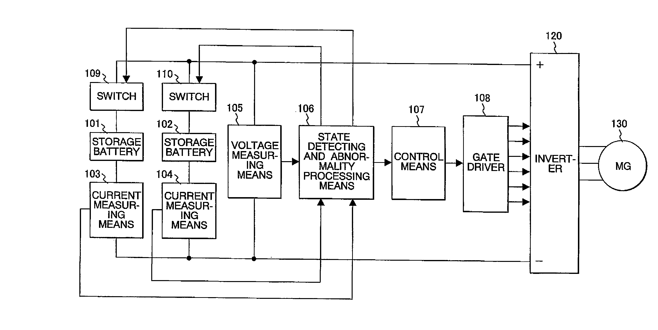
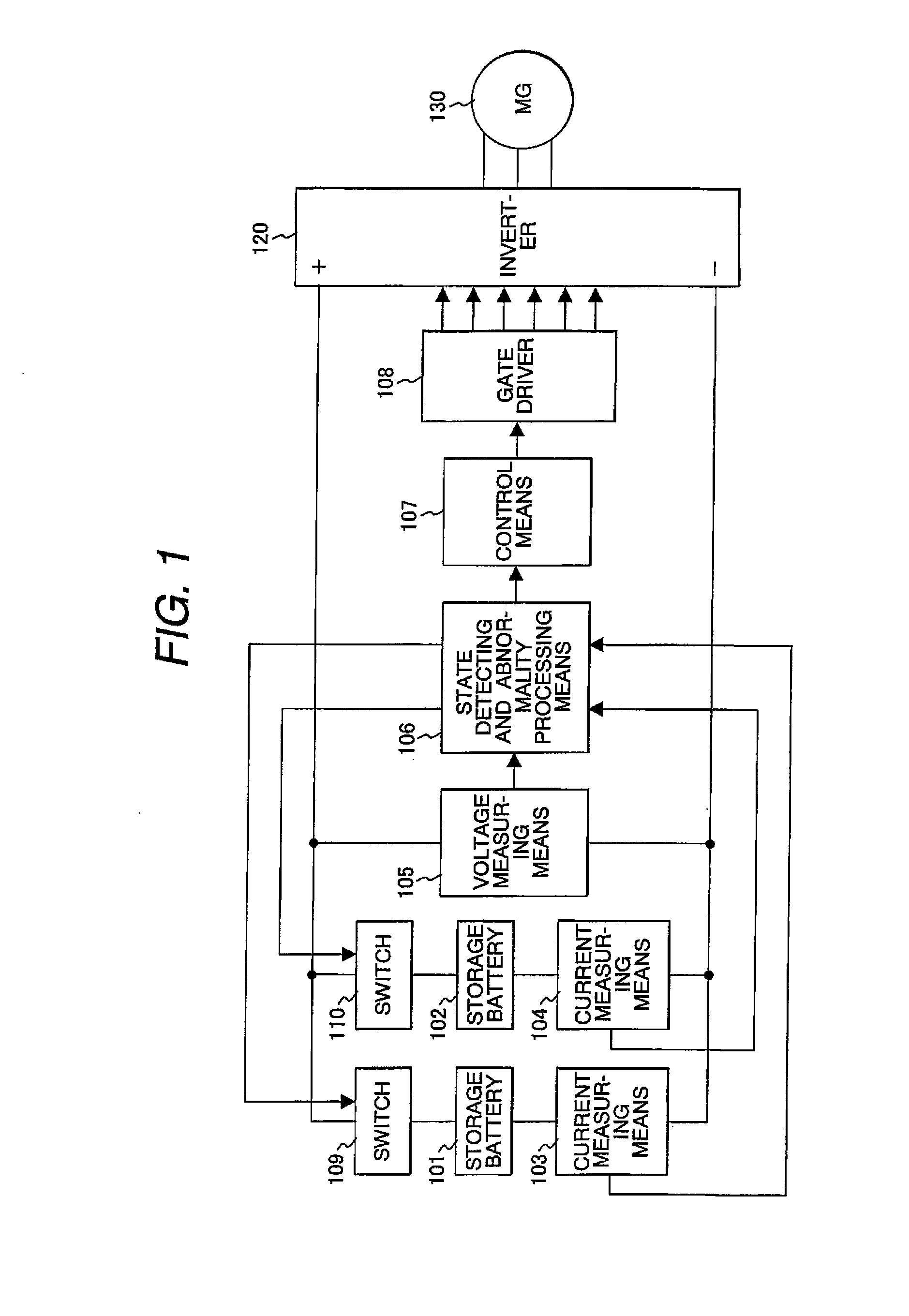
[0022]FIG. 1 is a whole block diagram of the storage battery control system for a hybrid vehicle of Embodiment 1 of the present invention. Firstly, the system includes storage batteries 101 and 102 connected in parallel for storing and discharging electricity, current measuring means 103 and 104 for measuring currents at time of no-load of the storage batteries and during charging and discharging, and a voltage measuring means 105 for measuring voltages at both ends of the parallel connection circuit of the two storage batteries 101 and 102. To detect the state of the storage batteries 101 and 102 on the basis of measured results of the current measuring means 103 and 104 and voltage measuring means 105, a state detecting and abnormality processing means 106 is installed. On the basis of information from the state detecting and abnormality processing means 106, the system drives a gate driver 108 via a control means 107 and controls an inverter 120. The AC side of the inverter 120 i...
embodiment 2
[0043] In Embodiment 2, the process contents of the state detecting and abnormality processing means 106 described in Embodiment 1 are changed. The other functions are the same as those of Embodiment 1.
[0044]FIG. 5 is a process flow chart for explaining the process contents of the state detecting and abnormality processing means 106 of Embodiment 2 of the present invention. The state detecting and abnormality processing means 106 executes state detection of the storage batteries 101 and 102, which are connected in parallel, in real time. The state detecting and abnormality processing means 106, when detecting at Step 501 a faulty storage battery among the storage batteries 101 and 102 connected in parallel, turns off at Step 502 the switch 109 or 110 corresponding to the faulty storage battery and separates the faulty storage battery. Next, at Step 503, similarly to Embodiment 1, the state detecting and abnormality processing means 106 executes an allowable current restriction acco...
embodiment 3
[0046] Further, as Embodiment 3 of the present invention, Embodiments 1 and 2 can be combined. Namely, when a faulty storage battery occurs, (1) the charging and discharging current according to the number of faulty storage batteries is restricted, (2) the allowable SOC range is shifted high, (3) only the discharging current is restricted furthermore, and (4) when a motor assist is necessary, the restriction of the discharging current of Item (3) is canceled.
[0047]FIG. 6 is an illustration for the SOC and allowable discharging current of Embodiment 3 of the present invention. Firstly, under normal condition, an allowable range 1 of SOC of the storage batteries is assumed as 40% to 60% from a lower limit LL1 to an upper limit UL1. Here, a fault (an abnormality) occurs in one storage battery, and the faulty storage battery is separated, and as specified at Step 403 shown in FIG. 4, a restriction 601 for the charging and discharging current according to the number of storage batteries...
PUM
 Abstract
Description
Claims
Application Information