Control system for multiphase rotary electric machine

Active Publication Date: 2007-10-25
DENSO CORP
View PDF19 Cites 48 Cited by
  • Summary
  • Abstract
  • Description
  • Claims
  • Application Information

AI Technical Summary

Benefits of technology

[0011]The present invention has been made in view of the problems provided above and has as its object to provide a control system for multiphase rotary electric machines, in which the output of a multiphase rotary electric machine is controll

Problems solved by technology

In the above configuration, malfunction in the inverter may not allow appropriate torque control of

Method used


Image

  • Control system for multiphase rotary electric machine
  • Control system for multiphase rotary electric machine
  • Control system for multiphase rotary electric machine

Examples


first embodiment

[0058]Hereinafter is described a first embodiment of the present invention with reference to the accompanying drawings. In the present embodiment, a control system for multiphase rotary electric machines of the present invention is applied to a system loaded on a hybrid vehicle.

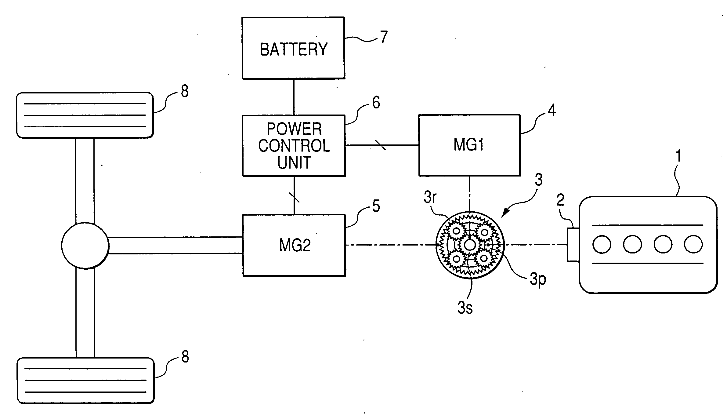
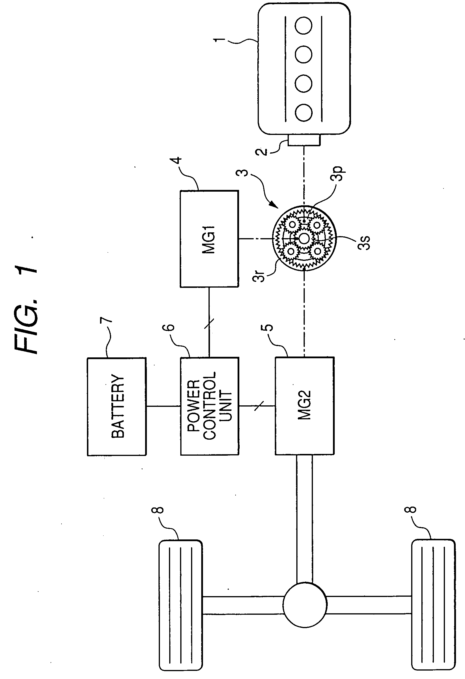
[0059]FIG. 1 is a schematic diagram illustrating a general configuration of a power transmission system of the hybrid vehicle mentioned above.

[0060]As shown in FIG. 1, an internal combustion engine 1 is provided with a flywheel damper 2 for suppressing vibration of the internal combustion engine 1. The motive power of the internal combustion engine 1 is distributed to a first motor-generator (generator 4) and a second motor-generator (motor 5) through a torque-splitting mechanism 3. In particular, the torque-splitting mechanism 3 is made up of a planetary gear mechanism. In the planetary gear mechanism, a planetary gear 3p is connected to a rotary shaft of the internal combustion engine, a sun gear 3s is conn...

second embodiment

[0117]Hereinafter is described a second embodiment of the present invention focusing on the differences from the first embodiment and referring to the accompanying drawings. In the present embodiment and in the following several embodiments, the identical or similar components to those in the first embodiment are given the same references for the sake of simplifying or omitting explanation.

[0118]FIG. 14 illustrates the generator 4, the inverter 10 and the microcomputer 50 associated with the present embodiment.

[0119]As shown in FIG. 14, the present embodiment is provided with switching circuits 130, 132 and 134 connecting between the outputs of respective arms of the inverter 10 and the three phases of the generator 4. These switching circuits 130, 132 and 134 are of normally-closed type which, however, may preferably be the ones not closed once brought into an open state. These switching circuits 130, 132 and 134 may be relays provided to an output bus bar, for example.

[0120]FIG. 1...

third embodiment

[0124]Hereinafter is described a third embodiment according to the present invention focusing on the differences from the second embodiment and referring to the accompanying drawings.

[0125]FIG. 16 illustrates a procedure, according to the present embodiment, for processes carried out at the occurrence of short circuit. These processes are carried out in predetermined cycles, for example, by the microcomputer 50.

[0126]In this series of processes, when any one of the switching elements 12, 14, 16, 18, 20 and 22 is determined as short-circuited (step S40), it is determined, at step S42, whether or not opening operation has already been performed for the switching circuits 130, 132 and 134. In this regard, it is assumed that the switching circuits 130, 132 and 134 keep a closed state once they are opened. Accordingly, in case the opening operation has once been performed, the series of processes shown in FIG. 16 is ended.

[0127]On the other hand, in case no opening operation has been per...


PUM


Abstract

A control system for multiphase rotary electric machines is provided. The control system carries out control of the output of a multiphase rotary electric machine by operating switching elements of an inverter, so that more appropriate measure can be taken when malfunction has occurred in the inverter. A rotary shaft of an internal combustion engine, a rotary shaft of a generator and a rotary shaft of a motor are linked through a torque-splitting mechanism. The control system carries out failsafe processes, at the occurrence of short circuit in a switching element of the inverter, to control load torque of the generator so as to prevent rotation of a rotary shaft of the internal combustion engine in a non-operative state, which rotation is induced by a motive force of the motor.

Description

CROSS-REFERENCE TO RELATED APPLICATION[0001]This application is based on and claims the benefit of priority from earlier Japanese Patent Application Nos. 2006-116602 and 2006-286739 filed Apr. 20, 2006 and Oct. 20, 2006, respectively, the descriptions of which are incorporated herein by reference.BACKGROUND OF THE INVENTION[0002]1. Technical Field of the Invention[0003]The present invention relates to a control system for multiphase rotary electric machines for controlling output of a multiphase rotary electric machine by operating switching elements of the inverter.[0004]2. Related Art[0005]A control system is known in which output torque of a three-phase motor is controlled with the operation of switching elements of an inverter. The inverter in this control system has three arms for bringing each of the three phases of the three-phase motor into electrical conduction with either a positive or negative side of a power supply voltage. In the control performed by this system, a shor...

Claims


Application Information

Patent Timeline
IPC IPC(8): B60K1/02B60L8/00
CPCB60K1/02Y02T10/70B60K6/445B60K6/52B60L11/14B60L2240/421B60W10/06B60W10/08B60W20/00B60W50/04B60W2510/081B60W2710/0644H02M1/38H02P29/022Y02T10/6265Y02T10/6286Y02T10/642Y02T10/7077Y02T10/6239Y10T477/23B60K6/365H02P21/00H02P29/032B60L50/16Y02T10/64Y02T10/62Y02T10/7072B60W20/50
Inventor TSUJI, HIROYAKAWASAKI, SHINGOMIYACHI, JUNJI
Owner DENSO CORP
Why Eureka
Try Eureka