
High pressure balloon

a balloon and high-pressure technology, applied in the field of high-pressure balloons, can solve the problems of large vessels in which the access device is connected, and achieve the effect of improving the air quality and reducing the risk of balloon damag

Active Publication Date: 2007-10-25
BOSTON SCI SCIMED INC
View PDF63 Cites 75 Cited by
  • Summary
  • Abstract
  • Description
  • Claims
  • Application Information

AI Technical Summary

Benefits of technology

[0006] The invention pertains to fiber reinforced laminate composite balloons and processes for preparing laminate compos

Problems solved by technology

Moreover, frequently the vessels into which the access devices are connected are quite large.

Method used


Image

  • High pressure balloon
  • High pressure balloon
  • High pressure balloon

Examples


example

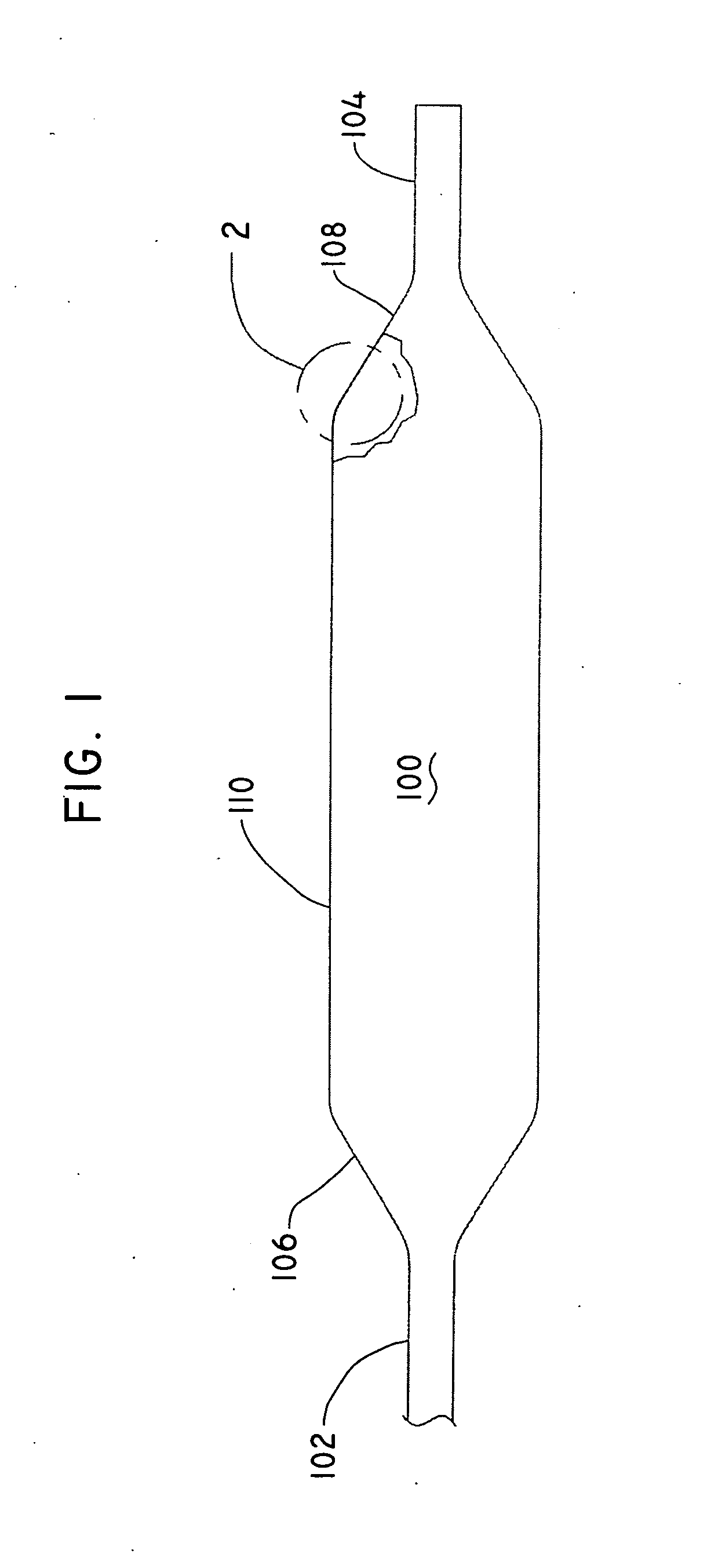
[0083] Underlayer balloons were prepared by radial expansion of extruded tubes of Pebax® 7233 polymer. The underlayer balloons had an average double wall thickness in the body region of approximately 0.0016 inches, a molded diameter of approximately 8 mm and a molded body length of approximately 2 cm. The underlayer balloons were sterilized with ethylene oxide according to a conventional protocol. At this stage, three balloons were retained, unbraided, as controls for comparison purposes.

[0084] The underlayer balloons were heat-sealed at their distal end. The proximal end was connected to a pneumatic syringe and pressurized balloon component to a firm stiffness (1-2 atm internal pressure).

[0085] A coating of pressure sensitive adhesive, HL-2081 from H. B. Fuller, was applied to the exterior surface of the underlayer balloon by hand dipping the pressurized balloon component into a solution of 25% adhesive in Toluene, drawing the balloon component out of solution and allowing it to ...


PUM

PropertyMeasurementUnit
Linear densityaaaaaaaaaa
Diameteraaaaaaaaaa
Thicknessaaaaaaaaaa

Abstract

Composite fiber reinforced balloons for medical devices are prepared by applying a web of fibers to the exterior of a preformed underlayer balloon, encasing the web with a matrix material to form an assembly, and inserting the assembly into a preformed outer layer balloon to form the composite balloon.

Description

BACKGROUND OF THE INVENTION [0001] Medical devices comprising catheter shafts and catheter balloons are used in an increasingly widening variety of applications including vascular dilatation, stent delivery, drug delivery, delivery and operation of sensors and surgical devices such as blades, and the like. The desired physical property profile for the balloons used in these devices varies according to the specific application, but for many applications a high strength robust balloon is necessary and good softness and trackability properties are highly desirable. [0002] Commercial high strength balloons having wall strengths in excess of 20,000 psi have been formed of a wide variety of polymeric materials, including PET, nylons, polyurethanes and various block copolymer thermoplastic elastomers. A particular application which has a very high pressure requirement is reopening of stenoses which develop at or in long-term shunt, ports or grafts employed for repeated blood access, for in...

Claims


Application Information

Patent Timeline
IPC IPC(8): A61M29/00
CPCA61M25/1029A61M25/104A61M2025/1075A61M2025/1084A61M25/10A61L29/143Y10T428/1386A61L29/049Y10T428/1372Y10T428/1362Y10T428/1366Y10T428/1352Y10T428/1334A61M25/1002B32B5/02B32B5/28B32B5/22B32B5/24B32B1/00A61M2205/0216C08L23/06C08L75/04C08L77/00A61L29/14A61M2025/1088
Inventor HORN, DANIEL J.CHEN, JOHN J.XIONG, YINGKHAMMOUNGKHOUNE, JOEBLIX, JOHNKHIEU, AARON
Owner BOSTON SCI SCIMED INC
Learn More