
Electric pencil sharpener

a technology of electric pencils and sharpeners, which is applied in the direction of sharpeners, printing, writing accessories, etc., can solve the problems of inability to operate the sharpener, the situation becomes hopeless, and the sharpener is even more troublesome to remov

Inactive Publication Date: 2007-11-01
KTF
View PDF0 Cites 19 Cited by
  • Summary
  • Abstract
  • Description
  • Claims
  • Application Information

AI Technical Summary

Benefits of technology

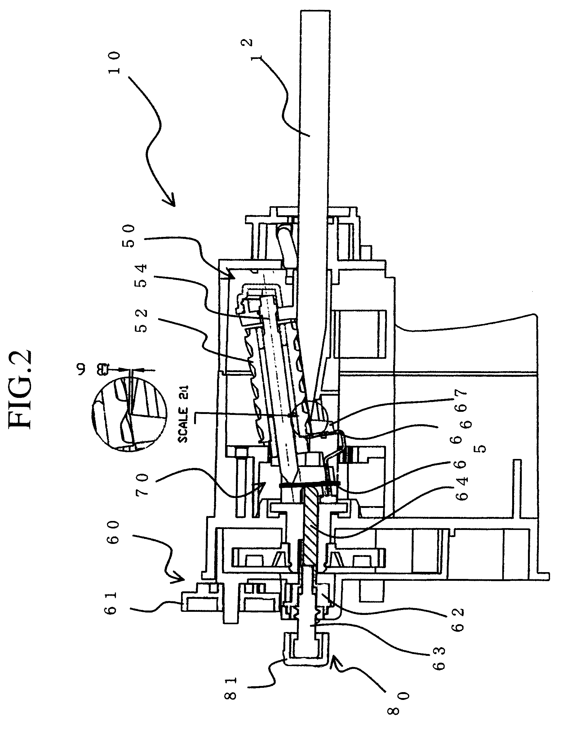
[0015]The present invention also provides an electric pencil sharpener wherein the wasteful shaving prevention mechanism has a structure whereby even when rotation of the pencil-core tip adjustment dial causes rotation of a pencil-core tip adjustment gear (formed integrally with a pencil-core tip adjustment internal gear), the gear shaft itself is moved to move the connecting rod, so that movement of the gear shaft moves the connecting rod to press the swinging end of the swing plate provided on the end of the connecting rod and interoperatively move the shaft of the cutting blade and thus move the cutting blade upward to separate the cutting blade from the shaved surface of the pencil being shaved, thereby preventing wasteful shaving.
[0021]Owing to the structure explained in the foregoing, the electric pencil sharpener according to the present invention offers the following merits:1. Although the provision of the core fragment removal mechanism inside the pencil-core tip adjustment mechanism somewhat complicates the internal structure, the overall size and ease of use are comparable to those the conventional sharpener and cost is held to a low level. In addition, the conventional wasteful shaving prevention mechanism is incorporated without modification, so that the advantages of the conventional sharpener, specifically that the power is not turned OFF when the diameter of the pencil-core tip reaches a predetermined size and that the pencil is not made hard to extract by the cutting blade biting into the pencil, are also thoroughly built in.2. Since the pencil-core tip adjustment mechanism and core fragment removal mechanism are formed using a single common screw member, the sharpener has a simple structure as a whole and can be made compact by simplifying its internal structure.3. Since the wasteful shaving prevention mechanism is provided as a standard feature, the electric pencil sharpener does not sacrifice any advantages despite being multifunctional.
[0022]4. The electric pencil sharpener enables fine adjustment of the pencil core-tip thanks to the provision of the through-hole at the center of the pencil-core tip adjustment screw of the pencil-core tip adjustment mechanism so as to establish a structure that enables the gear shaft to move freely in the axial direction.5. Although the fact that the structure of the core fragment removal mechanism is such that the pencil-core tip adjustment screw and gear shaft of the pencil-core tip adjustment mechanism move as a whole when the button is pressed makes the structure of the electric pencil sharpener somewhat complex, a product can be provided that remains unchanged overall in the general configuration of the electric pencil sharpener and that has the advantages of being compact and inexpensive for its broad range of functions. In addition, a pencil stub, broken off core fragment or other remaining object can be removed.6. The switchbox for sensing pencil insertion enables operation with a simplified structure, thus enabling size reduction.7. The substantially triangular shape of the perforated section establishes play at the contact surface, thereby ensuring reliable operation.8. The slide plate, adapter plate and adjustment lever make it possible to conduct true center pencil sharpening.9. Since the surface of the slide plate that makes contact with the pencil is a flat plate that can be imparted with curvature, the pencil can be reliably retained.

Problems solved by technology

While removal of a broken off piece of pencil-core from a hand-operated pencil sharpener can become quite an ordeal for the lack of any standard procedure for achieving this end, removal from an electric pencil sharpener is even more troublesome.
This is because an electric pencil sharpener may suffer ill effects if picked up and turned over, and if the broken-off core piece should become lodged deep inside the sharpener, the situation becomes hopeless, i.e., the sharpener can no longer be operated.
Moreover, improvement of pencil sharpener performance does not eliminate the possibility of pencil-core fragments remaining inside.
In other words, this is not a problem that can be overcome by enhancing pencil sharpener performance but a problem that inevitably occurs because of various related factors, such as the pencil-core hardness, defects occurring during pencil manufacture, and impacts imparted in the course of use as when, for example, the writer drops the pencil.
Although some existing electric pencil sharpeners are equipped with a wasteful shaving prevention mechanism utilizing the method of shutting off the driving power when sharpening is complete and with pencil-core tip adjustment and core fragment removal mechanisms, they are inconvenient in the point of producing a rough shaved surface owing to the sudden shutoff of driving power when sharpening is finished.
However, considerably complexity is encountered in providing a single electric pencil sharpener with all of these capabilities, i.e., the wasteful shaving prevention capability utilizing the method of stopping the cutting operation by cutting blade separation, the pencil-core tip adjustment capability, and the core fragment removal capability by pencil-core ejection, and, therefore, no electric pencil sharpener incorporating all of the capabilities in a single unit has been available heretofore.
Since the provision of multiple features in a sharpener tends to increase both weight and overall size, and also increases cost, a need has been felt for the development of an inexpensive sharpener of simple structure that incorporates all of the functions required by customers with no increase in size or weight relative to those of the conventional sharpener.

Method used


Image

  • Electric pencil sharpener
  • Electric pencil sharpener
  • Electric pencil sharpener

Examples


first embodiment

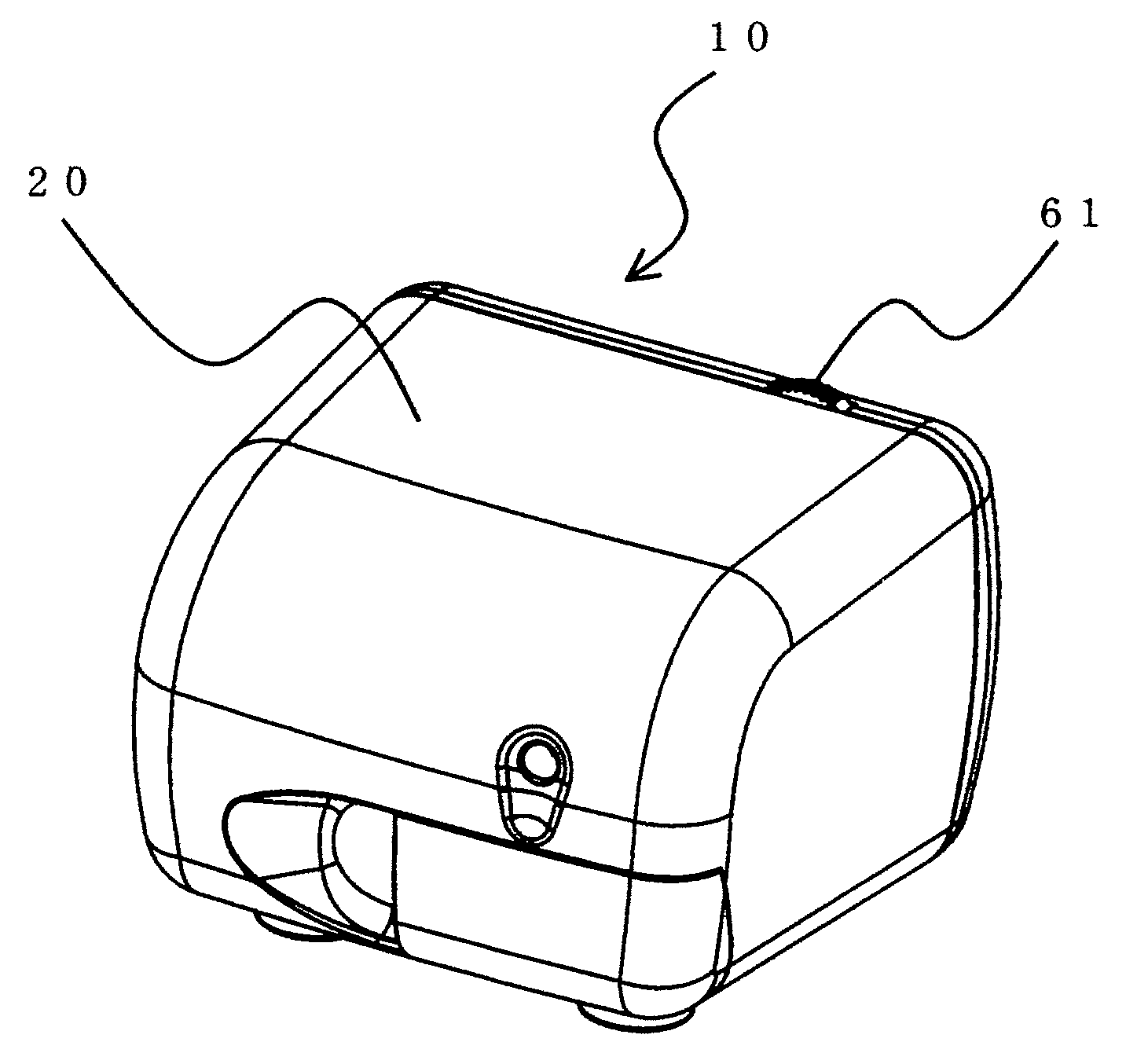
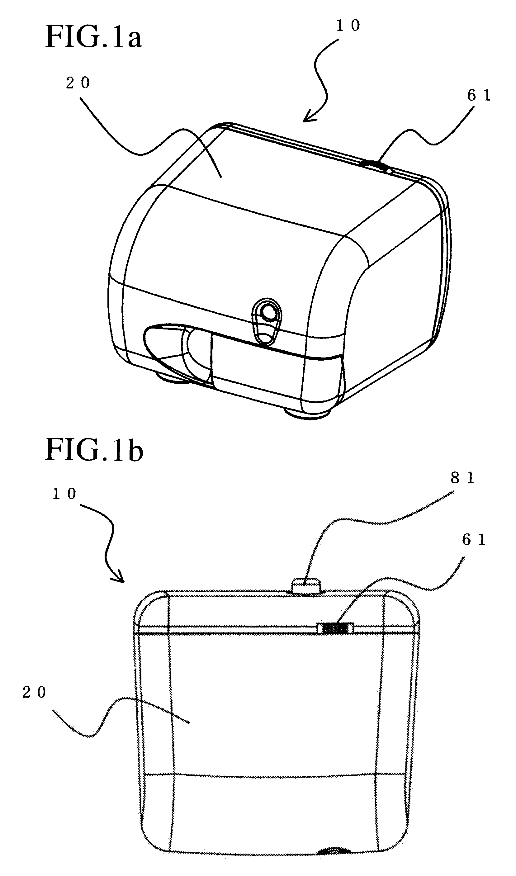
[0039]The main unit cover 20 has an overall box-like shape. A pencil-core tip adjustment dial 61 and a button 81 of the core fragment removal mechanism 80 are provided to project outward of the surface of the main unit cover 20. A pencil insertion hole is formed at a location opposite that of the button of the core fragment removal mechanism.

[0040]The drive mechanism, transmission mechanism, cutting mechanism, pencil-core tip adjustment mechanism, wasteful shaving prevention mechanism and core fragment removal mechanism are accommodated inside the main unit cover.

[0041]The drive mechanism 30 comprises a drive device 32 and an electric power supply unit 34. The drive device 32 is a motor in this embodiment. A gear is fitted on the output shaft of the motor. Power is transmitted from the motor 32 to the transmission mechanism 40 through this gear. In this embodiment, the electric power supply unit 34 is an ac power source but can instead be a dc power source.

[0042]The drive mechanism ...

second embodiment

[0056]In a second embodiment of the present invention, the functions of the pencil-core tip adjustment mechanism 60 and the core fragment removal mechanism 80 are simultaneously enabled by a single operating unit. The electric pencil sharpener according to the second embodiment is the same in operating principle as the first embodiment but differs in structure, as explained in the following. As shown in FIG. 5, the pencil-core tip adjustment dial 61 and button 81 constituted as separate members in the first embodiment are structured unitarily as a pencil-core tip adjustment knob 90. (The orientation of the embodiment shown in FIG. 5 is reversed from that in FIG. 2.) When the pencil-core tip adjustment knob 90 is turned, the screw thread provided thereon causes it move inward and press against an engagement member 100. Since the engagement member 100 in turn presses against a shaft 110, the tip of the shaft 110 presses against the central region of a swing plate 120 whose one end is ...

third embodiment

[0058]A third embodiment of the present invention is imparted with various functions by configuring the switchbox for sensing a pencil inserted into the electric pencil sharpener as illustrated in the drawings.

[0059]As shown in FIG. 6, a switchbox 150 comprises a pencil insertion zone switch lever 160, a switch plate 170, a switch 180, a shaving bin detector 190, and a switch lever 200.

[0060]The pencil insertion zone switch lever 160 is configured so that a projection protruding into the pencil insertion hole pushes it out of the hole horizontally upon entry of a pencil, thereby operating an insertion section switch 162. It has the general shape of the letter L and comprises a perforated section 164 formed with a hole and a switch lever projection 166.

[0061]The switch plate 170 is configured to press the terminal 182 of the switch 180 when a switch plate projection 172 thereof is pressed by the switch lever projection 166.

[0062]The switch 180 is connected to the current source and o...


PUM


Abstract

An electric pencil sharpener comprises a wasteful shaving prevention mechanism for separating the rotatable cutting blade from the pencil a pencil-core tip adjustment mechanism for adjusting the diameter of the shaved pencil-core tip, and a core fragment removal mechanism for removing any broken off pencil-core fragment remaining in the electric pencil sharpener. The wasteful shaving prevention mechanism includes the cutting blade, a cutter shaft and a plate and is structured to separate the cutting blade from the pencil when sharpening if finished. The pencil-core tip adjustment mechanism includes a pencil-core tip adjustment dial, a rotatable pencil-core tip adjustment screw, a gear shaft, a connecting rod, a plate and a stop. The core fragment removal mechanism includes a button, a gear shaft, a connecting rod, a plate and a stop. An electric pencil sharpener that further incorporates a pencil diameter adapter is also provided.

Description

BACKGROUND OF THE INVENTION[0001]1. Field of the Invention[0002]The present invention relates to an electric pencil sharpener that uses electric power to shave the tip of a pencil, particularly an electric pencil sharpener with enhanced functions including pencil-core tip adjustment capability, core fragment removal capability and wasteful shaving prevention capability, and further relates to an electric pencil sharpener equipped with a pencil diameter adapter.[0003]2. Description of Related Art[0004]Electric pencil sharpeners, which are widely used in both the home and office, are today in greater demand than the conventional manual pencil sharpener. The mainstream in pencil sharpeners is now the functionally enhanced electric pencil sharpener. Although rechargeable and dry battery sharpeners that offer high mobility are also available, development of multifunctional AC-powered electric pencil sharpener responsive to various requirements continues to move forward.[0005]One feature ...

Claims


Application Information

Patent Timeline
Patent Type & Authority Applications(United States)
IPC IPC(8): B43L23/00
CPCB43L23/02B43L23/008
Inventor TAKADA, TOKINORI
Owner KTF
Learn More