
Motor Control and Driver for Electric Boosting Application

a technology of electric boosting and motor control, which is applied in the direction of dynamo-electric converter control, programme control, dynamo-electric gear control, etc., can solve the problems of not providing an immediate power boost and taking a long time for the turbine to reach the necessary speed, and achieves high speeds

Active Publication Date: 2007-11-01
GARRETT TRANSPORATION I INC
View PDF9 Cites 15 Cited by
  • Summary
  • Abstract
  • Description
  • Claims
  • Application Information

AI Technical Summary

Benefits of technology

[0010] Hence, it is an object of the present invention to provide a system for driving a compressor which can be operated at high speeds.

Problems solved by technology

A main problem with turbochargers is that they do not provide an immediate power boost when it is requested, e.g., by operating an accelerator pedal in a vehicle.
Namely, it takes some time for the turbine to reach the necessary speed before a boost can be produced.

Method used


Image

  • Motor Control and Driver for Electric Boosting Application
  • Motor Control and Driver for Electric Boosting Application
  • Motor Control and Driver for Electric Boosting Application

Examples


Embodiment Construction

[0045] In the following, preferred embodiments of the invention are described.

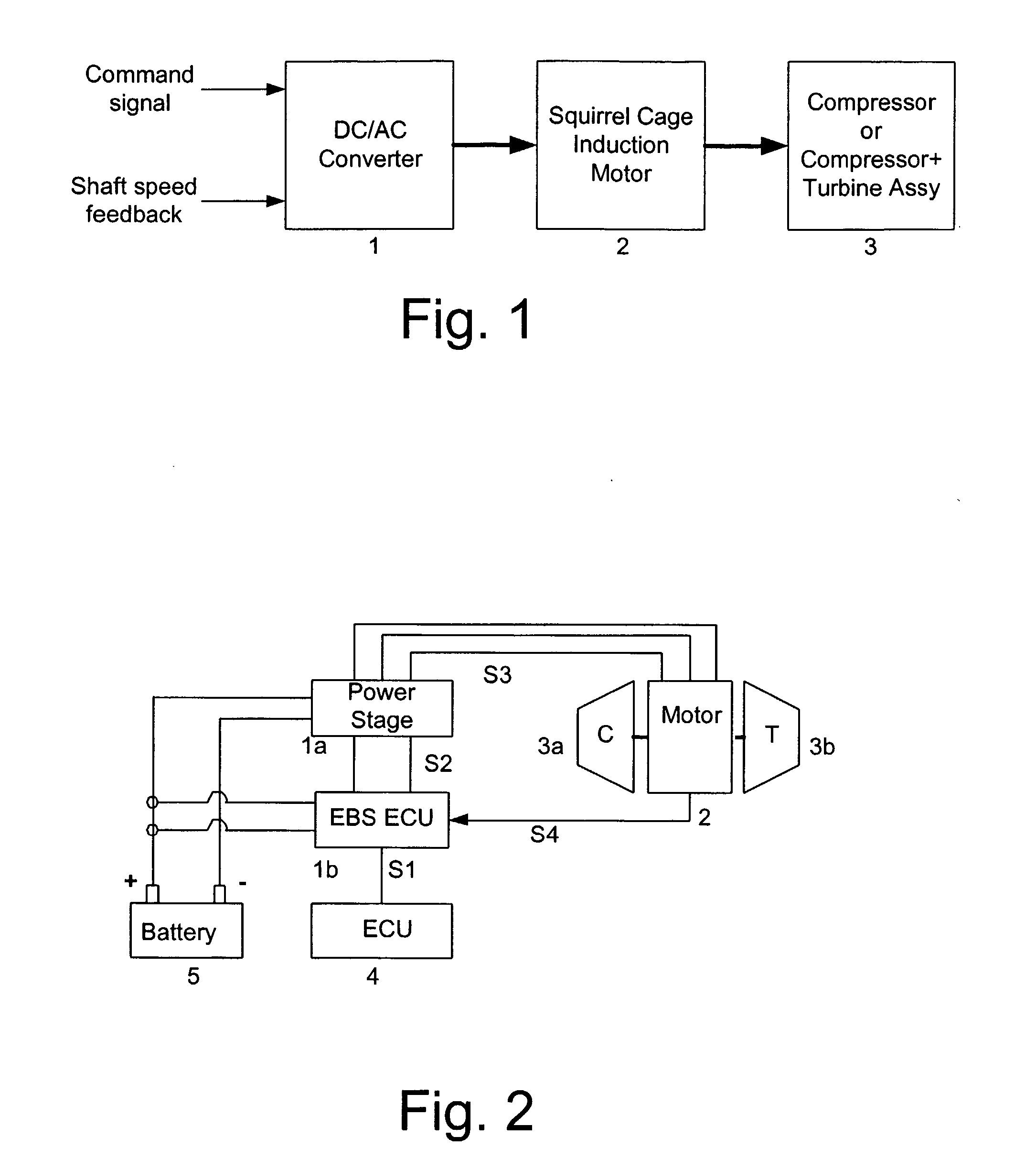
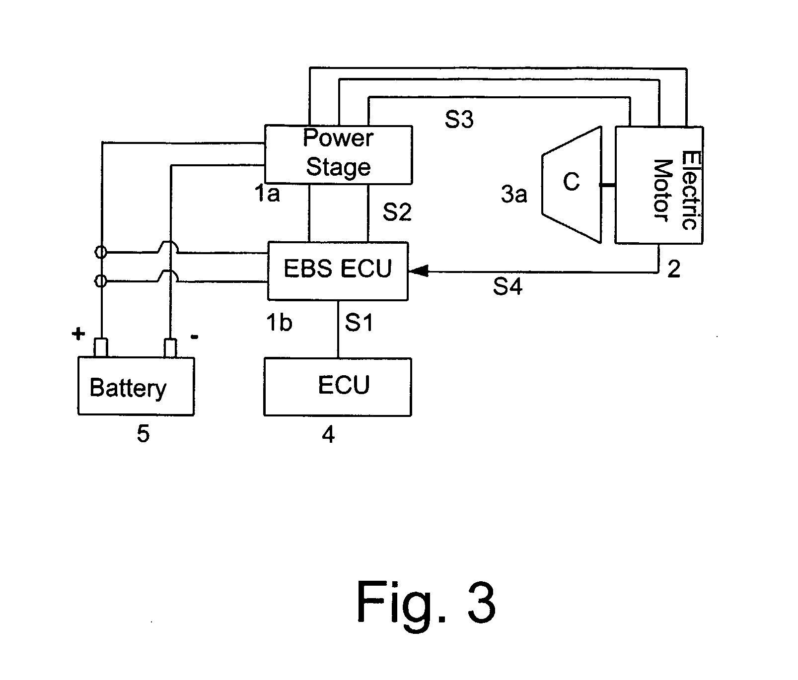
[0046] As already described above, the invention is directed to driving a turbocharger or an electrically driven compressor with an electric motor. That is, the invention can be used for an electrically driven compressor, or an electrically assisted turbocharger. In both case, the motor is switched on only during short transient phases where turbolag is to be compensated.

[0047] Such a system is also referred to as an electric boosting system (EBS). When adapting such a system in a vehicle, preferably the vehicle electrical network is used as an electrical power source. The electric motor and its electronic controller must have high speed capability (up to 250 kRPM), high low end torque, high overall efficiency and comply with high temperature environment. Moreover, in case a mass production is intended, low cost solutions are mandatory, particularly for the electronic controller.

[0048] Thus, the hardwar...


PUM


Abstract

The invention proposes a system for driving a compressor, comprising an induction motor (2) for driving the compressor (3), said induction motor including a squirrel cage rotor, and a controller (1) for controlling the induction motor, said controller comprising a memory for storing drive patterns for driving the induction motor, a first frequency generation means for generating a field frequency based on a field command and / or a second field generation means for generating a voltage frequency based on a voltage command, wherein a drive pattern in extracted from the memory based on the generated frequency or frequencies. Alternatively, the invention proposes a system for driving a compressor, comprising an induction motor (2) for driving the compressor (3), said induction motor including a squirrel cage rotor, and a controller (1) for controlling the induction motor, wherein the controller is adapted to distinguish between a steady state and a transient state of the induction motor.

Description

FIELD OF THE INVENTION [0001] The invention relates to a system for driving an electrically driven compressor, or an electrically assisted turbocharger. BACKGROUND OF THE INVENTION [0002] A compressor serves to compress air, and an important application thereof is the use in a turbocharger. A turbocharger compresses the air flowing into an engine in order to supply more air into a cylinder. In this way, more fuel can be added so that more power can be obtained from a cylinder compared to a case in which no turbocharger is used. [0003] A turbocharger is constituted by a compressor and a turbine, which is rotated by exhaust gas of the engine. The turbine, i.e., the turbine wheel is connected to the compressor wheel by a shaft. Hence, the rotation of the turbine drives the compressor, which in turn compresses ambient air supplied thereto and feeds it to the cylinder(s) of the engine. [0004] A main problem with turbochargers is that they do not provide an immediate power boost when it i...

Claims


Application Information

Patent Timeline
Patent Type & Authority Applications(United States)
IPC IPC(8): H02P27/06F02B31/00H02P21/00H02P23/00
CPCH02P23/0036H02P23/0004
Inventor BARTHELET, PIERREDEVULDER, NICOLASGREENTREE, CHRISLORANT, CEDRICPOUGET, STANISLAUSSTALSBERG, KEVINWESQUET, ALAIN
Owner GARRETT TRANSPORATION I INC
Learn More