
Thermal Type Flow Sensor

Inactive Publication Date: 2007-11-01
HITACHI LTD
View PDF7 Cites 19 Cited by
  • Summary
  • Abstract
  • Description
  • Claims
  • Application Information

AI Technical Summary

Benefits of technology

[0017]An object of the present invention is to eliminate such an unfavorable influence of pollution of the support for the heating resistor on output characteristics of a flow rate sensor (flow rate measuring device).
[0020]In the above structure, a minimum temperature point (point at which the temperature gradient becomes zero) can be make in the support's portions between the first and second heating resistors. Thereby the support for the first and second heating resistors can prevent heat transfer in an atmosphere of a fluid to be measured.

Problems solved by technology

As such soot volume increases over time, heat transmission between the support and the fluid to be measured (gas to be measured) would change from that before such deposition, the result would exert an unfavorable influence on output of the fluid flow sensor.
More specifically, as the rate of heat dissipation from the support to the atmosphere of the fluid to be measured changes depending on the degree of soot deposition, the rate of heat dissipation from the flow rate measuring heating resistor to the support would also change, so that the output value of the flow rate measuring heating resistor in relation to the gas flow rate before soot deposition would be different from that after soot deposition, resulting in a measurement error.
When the temperature of the second heating resistor is made equal to the temperature of the first heating resistor, heat transfer from the first heating resistor to the support is prevented to the some level but actually it is impossible to prevent such heat transfer completely.
However, even in the flow rate measuring device as described in Patent Document 1, when the flow rate measuring element (which is comprised of first and second heating resistors mounted on the support) is placed in an exhaust gas atmosphere, soot deposition on the support might change the level of heat dissipation from the support to the exhaust gas atmosphere, exerting an unfavorable influence on the flow rate measurement accuracy.

Method used


Image

  • Thermal Type Flow Sensor
  • Thermal Type Flow Sensor
  • Thermal Type Flow Sensor

Examples


Embodiment Construction

[0035]Next, embodiments of the present invention will be described referring to drawings.

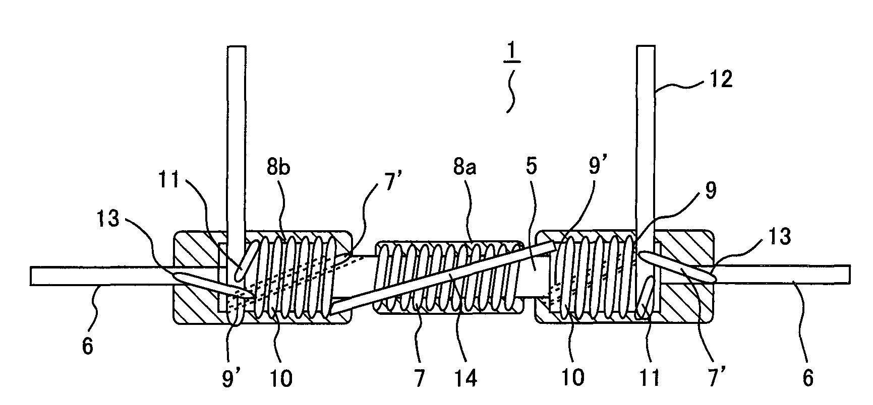
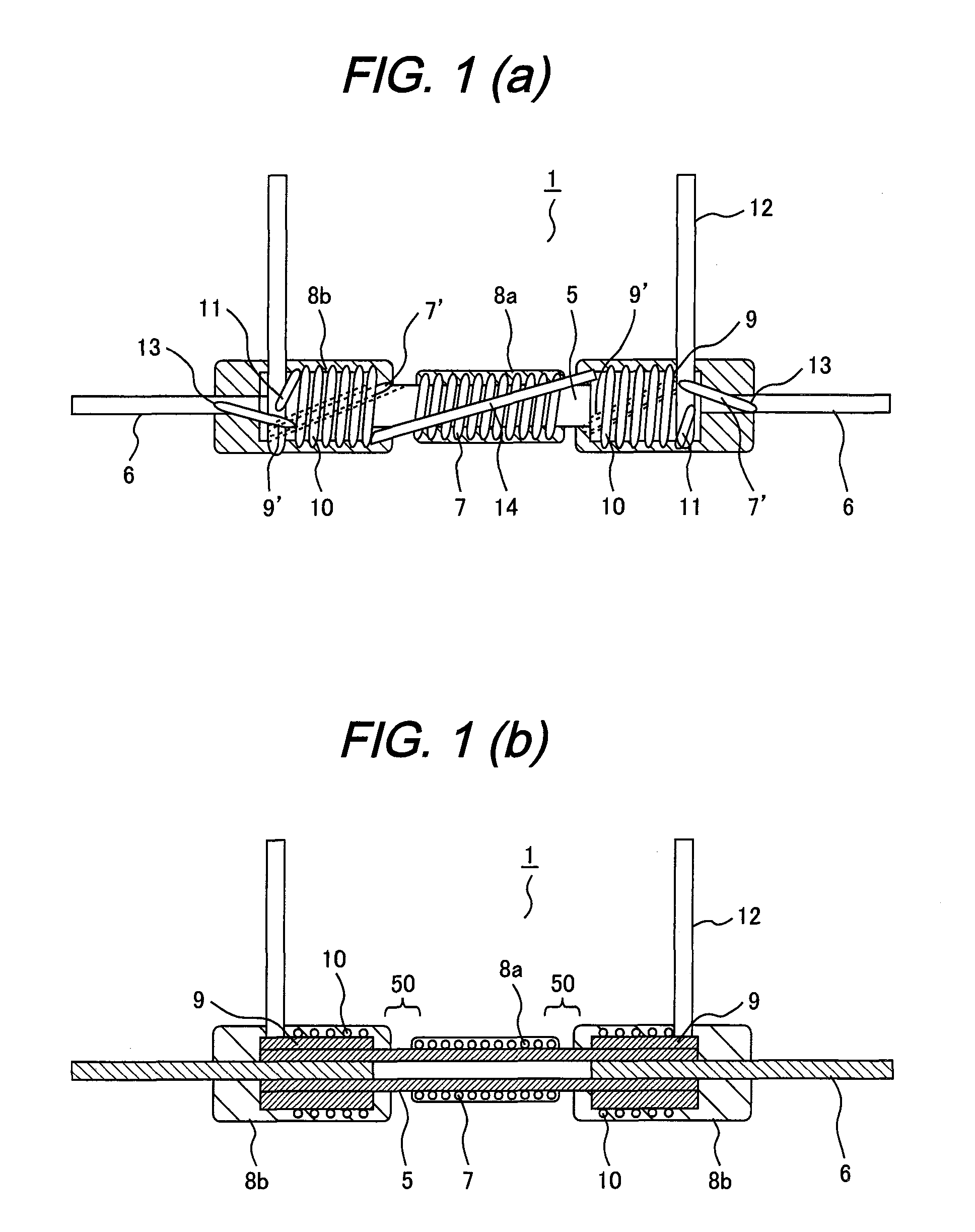
[0036]FIG. 1(a) is a partially sectional front external view of a measuring element (sensing section) in a thermal type flow sensor according to an embodiment of the present invention and FIG. 1(b) is a longitudinal sectional view of it.

[0037]The flow rate measuring element 1 is comprised of: a cylindrical support (first support) 5 for supporting a heating resistor 5; a temperature-dependent hot wire (first heating resistor) 7 for measuring a flow rate wound around the support 5; a temperature-dependent hot wire (a second heating resistor) 10 which is to heat the support and that is wound around the support 5 similarly via sleeves (second support) 9; terminal pins 6 for the first heating resistor which are provided at both ends of the support 5; and terminal pins 12 for the second heating resistors which are provided around the respective sleeves 9.

[0038]The cylindrical support 5 and the sleeves...


PUM


Abstract

A flow rate measuring element of a thermal type flow sensor is placed in the fluid to be measured. The element includes: a first heating resistor for measuring a flow rate; a second heating resistor for heating a support for the first heating resistor; and current control circuits and which control heating resistor supply current so that the temperature of the second heating resistor is higher than the temperature of the first heating resistor.

Description

CLAIM OF PRIORITY[0001]The present application claims priority from Japanese application serial no. 2006-110849, filed on Apr. 13, 2006, the content of which is hereby incorporated by reference into this application.BACKGROUND OF THE INVENTION[0002]The present invention relates to a thermal type flow sensor for measuring a mass flow rate of a fluid by using a heating resistor.[0003]A conventional typical thermal type flow sensor has two temperature-dependent heating resistors incorporated in a bridge circuit. One of these resistors is used as a heating resistor for measuring a flow rate, and designed to have a relatively small resistance value because a heating current is applied. The other resistor is used as a temperature compensating resistor for a fluid to be measured, and designed to have a larger resistance value than the heating resistor because it is used at room temperature. In such a bridge circuit, potentials at two midpoints are sent to an operational amplifier and the c...

Claims


Application Information

Patent Timeline
IPC IPC(8): G01F1/68
CPCG01F1/696G01F1/692G01F1/69G01F1/699G01F1/6983
Inventor SUKEGAWA, YOSHIHIROTOKUYASU, NOBORUKASHIO, KAORITERADA, DAISUKE
Owner HITACHI LTD
Learn More