
Multi-Structure Internal Heat Exchange Type Distillation Tower

Inactive Publication Date: 2007-11-01
KANSAI CHEM ENG CO LTD
View PDF8 Cites 4 Cited by
  • Summary
  • Abstract
  • Description
  • Claims
  • Application Information

AI Technical Summary

Benefits of technology

[0004] The present invention provides an internal heat exchange-type distillation column with even better utilization ratio of energy (efficiency of heat transfer).
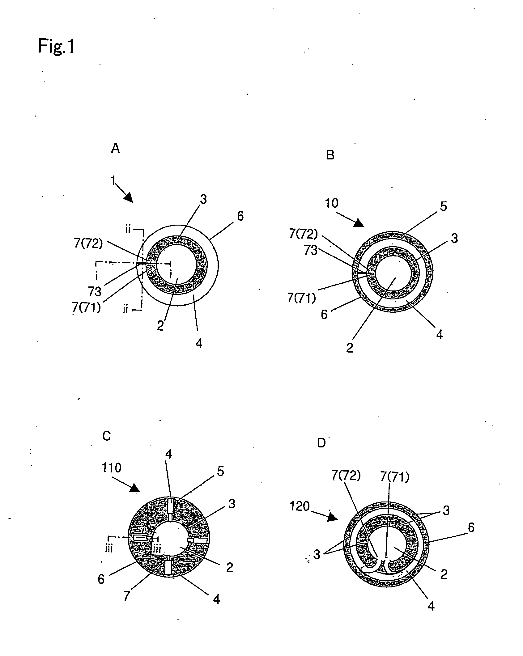
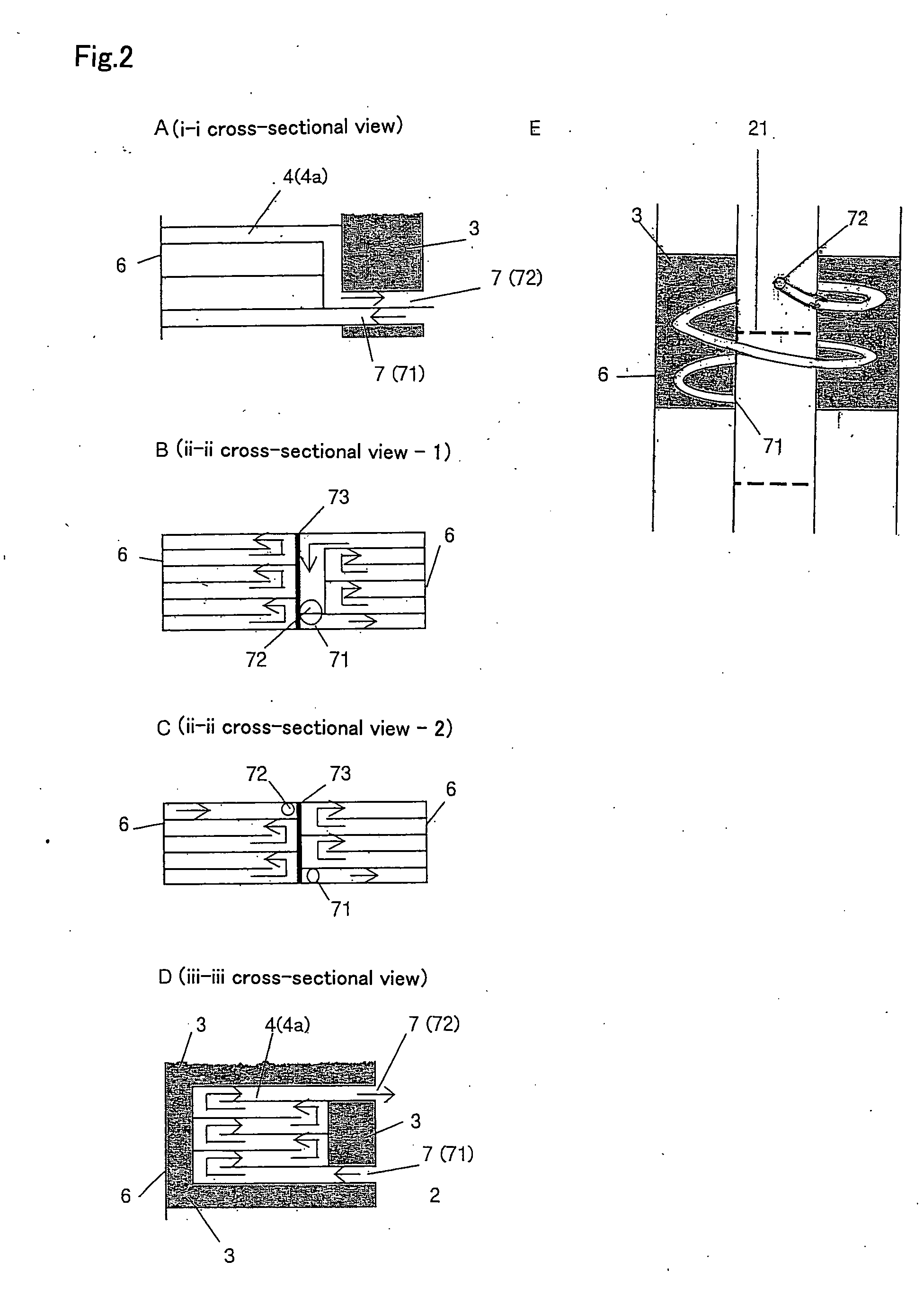
[0005] The present invention provides a multi-structured internal heat exchange-type distillation column comprising at least an outermost heat exchange section, an intermediate section, and an innermost heat exchange section; wherein the innermost heat exchange section is isolated from the intermediate section; wherein the outermost heat exchange section is also isolated from the intermediate section; wherein the outermost heat exchange section and the innermost heat exchange section are in communication with one another through at least two vapor tunnel connecting ports; wherein a channel is formed inside the outermost heat exchange section in such a manner that, in a case where at least one of the vapor tunnel connecting ports serves as an inlet for vapor from the innermost heat exchange section into the outermost heat exchange section, and the other vapor tunnel connecting port serves as an outlet for vapor from the outermost heat exchange section back to the innermost heat exchange section, the vapor can smoothly flow in one-way traffic from the inlet toward the outlet; and wherein either the outermost heat exchange section and the innermost heat exchange section, or the intermediate section, is a rectifying section, and the other is a stripping section.
[0013] In the multi-structured internal heat exchange-type distillation column of the present invention, the outermost heat exchange section and the innermost heat exchange section are in communication with one another and thus the internal heat transfer is carried out from both the inner and outer surfaces of the intermediate section. Further, the one-way traffic flow of vapor from the inlet to the outlet in the channel formed inside the outermost heat exchange section can make the vapor flow smoothly toward the outlet without any stagnant zone. Thus, by setting either the outermost and the innermost heat exchange sections or the intermediate section, as the high pressure side (high temperature side), and the other as the low pressure side (low temperature side), it is possible to provide an internal heat exchange type distillation column in which energy consumption is greatly reduced with very high efficiency of heat transfer.

Problems solved by technology

When a usual distillation process is performed using multi-stage distillation columns, there may arise the problem that energy consumption is very large.

Method used


Image

  • Multi-Structure Internal Heat Exchange Type Distillation Tower
  • Multi-Structure Internal Heat Exchange Type Distillation Tower
  • Multi-Structure Internal Heat Exchange Type Distillation Tower

Examples


example 1

[0039] The multi-structured internal heat exchange-type distillation column of the present invention will be described using the triple-structured internal heat exchange-type distillation column as an example. FIG. 4 is a front cross-sectional view of a triple-structured internal heat exchange-type distillation column 100 (hereinafter, referred to simply as “distillation column”). The distillation column 100 is constituted by the innermost heat exchange section 2, the intermediate section 3, and the outermost heat exchange section 4. The innermost heat exchange section 2 and the intermediate section 3 are isolated from one another, and the intermediate section 3 and the outermost heat exchange section 4 are also isolated from one another. The outer surface of the intermediate section 3 is in thermal contact with the outermost heat exchange section 4 and its inner surface is in thermal contact with the innermost heat exchange section 2. The outermost heat exchange section 4 is in com...

example 2

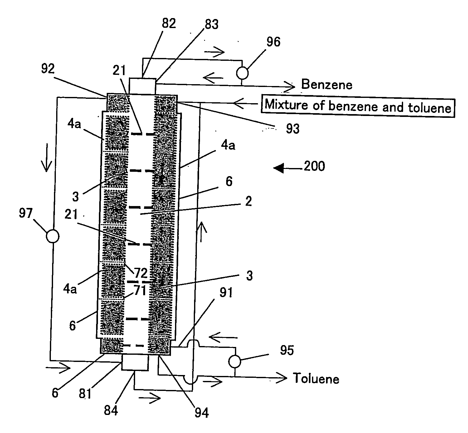
[0050] A triple-structured internal heat exchange-type distillation column as another embodiment of the present invention will be described with reference to FIG. 5. FIG. 5 is a front cross-sectional view of a triple-structured internal heat exchange-type distillation column (hereinafter, referred to simply as “distillation column”) 200. In the distillation column 200, the innermost heat exchange section 2 and the outermost heat exchange section 4 both serve as the rectifying section and the intermediate section 3 serves as the stripping section. In addition, the innermost heat exchange section 2 of the distillation column of FIG. 5 is equipped with trays 21. The reference numbers in FIG. 5 that are identical to those in FIG. 4 denote structures with the same functions as in FIG. 4.

[0051] As shown in FIG. 5, the outermost heat exchange section 4 of the distillation column 200 is made up of a plurality of outermost heat exchange chambers 4a that are installed independent of one anot...

example 3

[0057] Using the triple-structured internal heat exchange-type distillation column 200 of Example 2 of the present invention, the operation conditions for the rectification of a binary mixture of benzene and toluene will be described with reference to FIG. 6. The distillation column 200 shown in FIG. 6 comprises an innermost heat exchange section 2 and outermost heat exchange chambers 4a for the rectifying section and an intermediate section 3 serving as the stripping section. The innermost heat exchange section 2 is equipped with trays 21. In each outermost heat exchange chamber 4a, a single one-way traffic channel is formed spirally inside from the vapor inlet 71 to the vapor outlet 72 due to a baffle plate.

[0058] First, the feed solution of benzene / toluene mixture is supplied from the top of the stripping section, i.e. liquid inlet 93 into the intermediate section 3. The intermediate section 3 (stripping section) is set at a temperature distribution roughly estimated with the sp...


PUM


Abstract

The present invention provides a multi-structured internal heat exchange-type distillation column comprising at least an outermost heat exchange section, an intermediate section, and an innermost heat exchange section, in which the innermost heat exchange section is isolated from the intermediate section, the outermost heat exchange section is also isolated from the intermediate section, the outermost heat exchange section and the innermost heat exchange section are in communication with one another through at least two vapor tunnel connecting ports, a channel is formed inside the outermost heat exchange section in such a manner that, in a case where at least one of the vapor tunnel connecting ports serves as an inlet for vapor from the innermost heat exchange section into the outermost heat exchange section, and the other vapor tunnel connecting port serves as an outlet for vapor from the outermost heat exchange section back to the innermost heat exchange section, the vapor can smoothly flow in one-way traffic from the inlet toward the outlet, and either the outermost heat exchange section and the innermost heat exchange section, or the intermediate section, is a rectifying section, and the other is a stripping section. The distillation column of the present invention has excellent efficiency of internal heat exchange.

Description

TECHNICAL FIELD [0001] The present invention relates to a multi-structured internal heat exchange-type distillation column. BACKGROUND ART [0002] Distillation processes are very widely performed in many fields including the petrochemical industry. Multi-stage distillation columns are used in order to perform fractional distillation more precisely. When a usual distillation process is performed using multi-stage distillation columns, there may arise the problem that energy consumption is very large. Accordingly, internal heat exchange-type distillation columns have been proposed in order to utilize the energy efficiently. For example, Japanese Laid-Open Patent Publication No. 8-131704 discloses an internal heat exchange-type distillation column having a structure in which a single tube is inserted in the central section of a cylindrical main body, which forms a concentric double-tube structured column having a rectifying section inside the single tube and a stripping section outside ...

Claims


Application Information

Patent Timeline
IPC IPC(8): F28D7/00
CPCB01D3/14B01D3/26B01D3/166
Inventor NODA, HIDEOYAMAJI, HIROSHIKURATANI, NOBUYUKIKATAOKA, KUNIO
Owner KANSAI CHEM ENG CO LTD
Learn More