Hydraulic fitting

a technology of hydraulic fittings and fittings, applied in the direction of hose connections, screw threaded joints, branching pipes, etc., can solve the problems of prone to failure of known fittings, insufficient use of hydraulic systems by diesel engines, and failure of standard hydraulic fitting designs, etc., to avoid thin cross sections and high stress areas, simple and cost-effective design, and advantageous configuration

Active Publication Date: 2007-11-01
INT ENGINE INTPROP CO LLC
View PDF16 Cites 16 Cited by
  • Summary
  • Abstract
  • Description
  • Claims
  • Application Information

AI Technical Summary

Benefits of technology

[0005] A simple and cost effective design for a high pressure hydraulic fitting that is not prone to the failures experienced by the known designs is described herein. The hydraulic fitting may include a body having a central passage, a channel, a threaded section, and an extension section. The threaded section may be located between the channel and the extension section. The central passage may fluidly connect a first distal end with a second distal end of the body. A first o-ring may be located the channel. A locking nut may be engaged to the body. The locking nut may have an internal threaded section that is arranged to mate with the threaded section on the body. The new design avoids thin cross sections and high stress areas in the body, and is advantageously configured for compatibility with existing bore configurations, for example, bores conforming to the SAE J-2337 standard. The embodiments described herein may also advantageously be configured to accommodate seals of larger diameters than those specified in the SAE standards, enabling use of the fittings in applications with higher service pressures.

Problems solved by technology

In some applications having vibratory operational environments, for example, fittings used on internal combustion engines, the known fittings are prone to failure due to fractures and sealing issues.
Standard hydraulic fitting designs for hydraulic systems are often not adequate for use on diesel engines due to special high loading conditions encountered only on diesel engines.
For example, fittings conforming to the SAE J-2244 standard may fail due to exposure of the threads to high pressure oil.
Fittings conforming to the SAE J-2337 standard may fail due to high loads imparted to the fitting from engine vibrations, hose connections, hose loads, and hydraulic pressures.
Such fittings are partially effective in withstanding operation on a diesel engine environment, but are complex and costly.

Method used


Image

  • Hydraulic fitting
  • Hydraulic fitting
  • Hydraulic fitting

Examples


Embodiment Construction

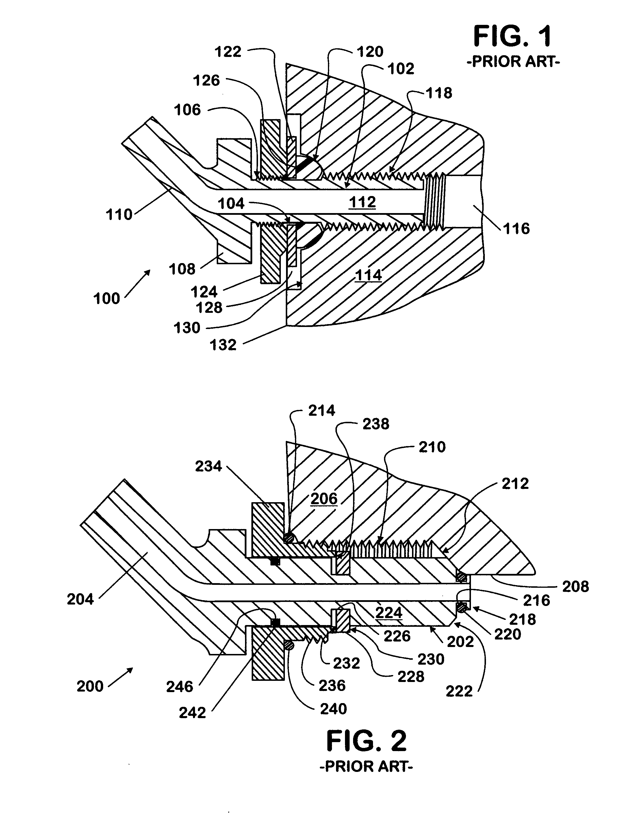
[0014] A known hydraulic fitting 100 is shown in cross section in FIG. 1. The fitting 100 may conform with SAE standards J-1926 and / or J-2244. The fitting 100 includes a mounting threaded section 102, a shank or circumferential channel portion 104, a jam-nut threaded section 106, a head section 108, and an outlet section 110, all connected to each other along and around an internal passage 112 extending clear through the fitting100. The threaded section 102 is constructed for insertion and attachment into a receiving component 114. The receiving component 114 has an opening, bore, or hole 116 for receiving the fitting 100 thereinto. The bore 116 may have a threaded section 118 arranged to mate with the threaded section 102. Adjacent to the threaded section 118 may be a chamfer section 120 that is arranged to be close to the shank section 104 when the fitting 100 is connected to the component 114.

[0015] A seal compression or retention ring 122 that is shaped as a washer may be assem...


PUM


Abstract

A high pressure hydraulic fitting (300) includes a body (302) having a central passage (322), a channel (304), a threaded section (314), and an extension section (310), wherein the threaded section (314) is disposed between the channel (304) and the extension section (314), and wherein the central passage (322) fluidly connects a first distal end (303) with a second distal end (316) of the body (302). A first o-ring (306) is in the channel (304). A locking nut (324) is engaged to the body (302). The locking nut (324) has an internal threaded section (326) that is arranged to mate with the threaded section (314) on the body (302).

Description

[0001] This invention relates to hydraulic systems for internal combustion engines, including, but not limited to, hydraulic fittings used on diesel engines. BACKGROUND OF THE INVENTION [0002] High pressure fittings for hydraulic applications are known. In some applications having vibratory operational environments, for example, fittings used on internal combustion engines, the known fittings are prone to failure due to fractures and sealing issues. Standard hydraulic fitting designs for hydraulic systems are often not adequate for use on diesel engines due to special high loading conditions encountered only on diesel engines. Examples of known fittings can be found in standards maintained by the Society of Automotive Engineers (SAE). For example, fittings conforming to the SAE J-2244 standard may fail due to exposure of the threads to high pressure oil. Fittings conforming to the SAE J-2337 standard may fail due to high loads imparted to the fitting from engine vibrations, hose con...

Claims


Application Information

Patent Timeline
Patent Type & Authority Applications(United States)
IPC IPC(8): F16L19/00
CPCF16L41/14F16L41/10Y10S285/918
Inventor DICKERSON, STEVEN J.CLARKE, STEVE H.
Owner INT ENGINE INTPROP CO LLC
Why Eureka
Try Eureka